+86 13520127780
 info@jingelway.com









Industrial Displacement Sensors: Types, Working Principles and Selection Guide
Release time: 2026-10-23
Industrial displacement sensors play an important role in machinery automation, motion control, hydraulic systems, structural monitoring, and industrial measurement.
Whether an engineer needs to monitor a 25mm machine movement, measure a hydraulic cylinder stroke, or track displacement over several metres, selecting the appropriate sensing technology is essential.
Different industrial displacement sensor types use different measurement principles, mechanical structures, and electrical output methods. A sensor suitable for compact packaging machinery may not be appropriate for long-stroke hydraulic equipment or outdoor structural displacement monitoring.
This guide explains the major types of displacement sensors, their working principles, advantages, limitations, and industrial applications. It also provides a practical selection framework for engineers, equipment manufacturers, and system integrators.
1. What Is an Industrial Displacement Sensor?
An industrial displacement sensor is a measurement device that detects a change in the position of an object relative to a defined reference and converts that movement into an electrical signal.
Displacement is commonly expressed in millimetres (mm) or micrometres (µm), depending on the application and measurement system.
Displacement sensors can measure:
- Linear movement along a defined axis
- Machine stroke and actuator extension
- Relative movement between mechanical components
- Position changes in hydraulic equipment
- Contact displacement in inspection fixtures
- Structural joint movement and localized deformation
A displacement sensor may also be called a position sensor, linear displacement transducer, or linear position sensor, although these terms are not interchangeable in every application.
Displacement vs Position Measurement
Displacement describes the change between two positions.
Position describes a location relative to a defined measurement reference.
For example, a position sensor may report a machine slide at 150mm along its calibrated stroke. If the slide previously occupied the 100mm position, the displacement is 50mm.
The ability to report position directly after power restoration depends on the sensing technology and system configuration.
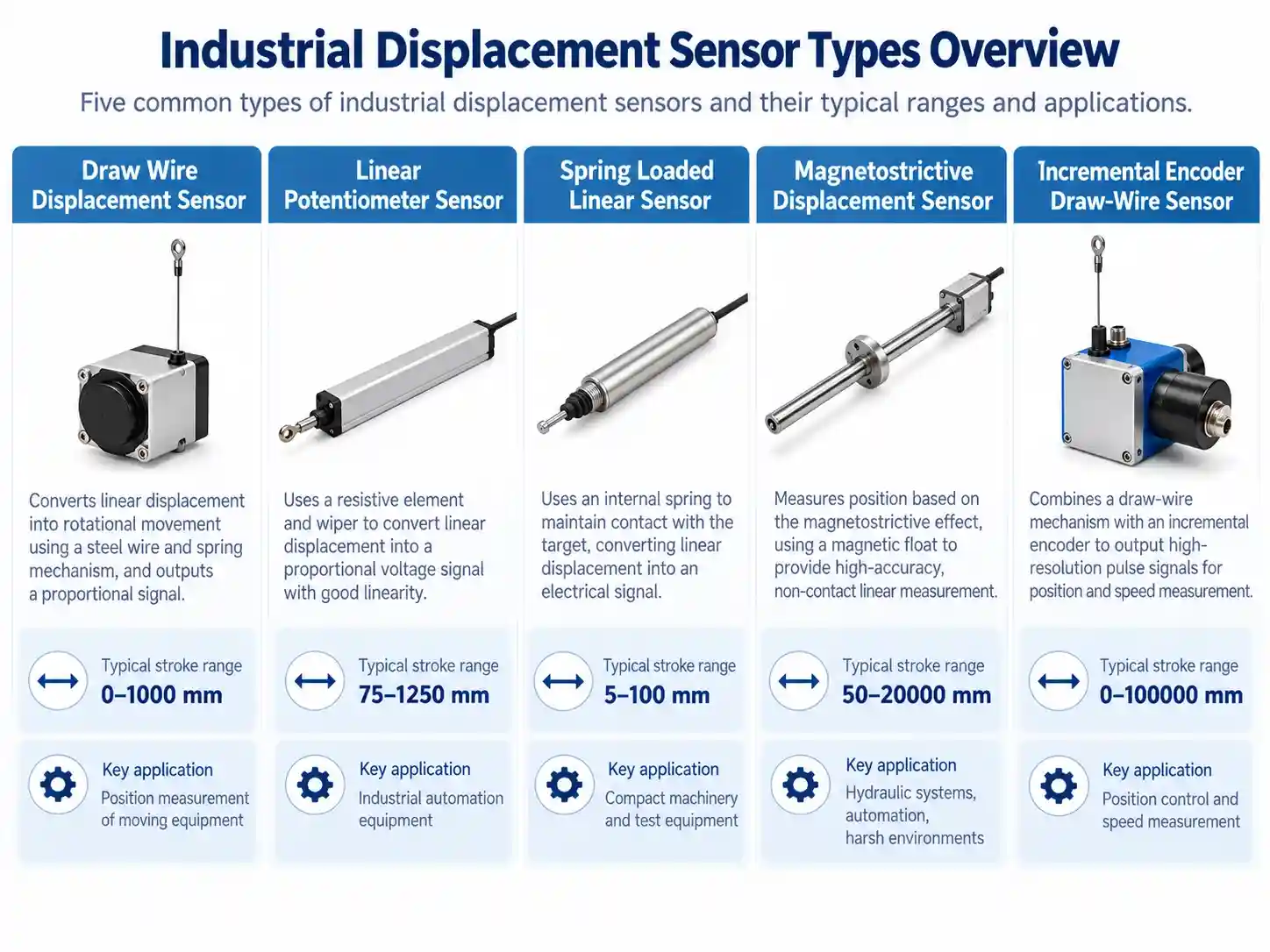
2. Main Types of Industrial Displacement Sensors
Several sensing technologies are used for linear industrial position measurement.
The most appropriate technology depends on measurement stroke, mechanical installation, output requirements, environmental conditions, and performance expectations.
2.1 Draw Wire Displacement Sensors
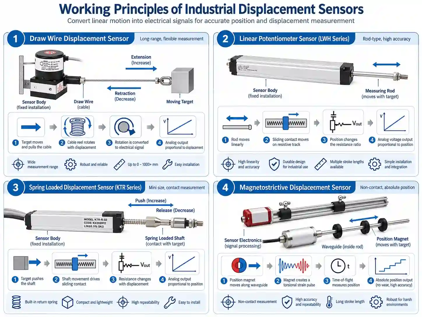
A draw wire displacement sensor, also known as a cable extension sensor, measures linear movement using a retractable measuring cable.
The sensor housing is mounted to a fixed reference point, while the cable endpoint is connected to a moving component.
When the target moves, the cable extends or retracts, rotating an internal spool.
The spool movement is measured using a compatible sensing element, such as a potentiometer or rotary encoder.
The output represents the linear movement of the cable endpoint.
Main advantages:
- Compact sensor housing relative to the measuring stroke
- Flexible installation between separated measurement points
- Suitable for machinery travel and movable structures
- Multiple output technologies depending on the model
- Available for short, medium, and long measuring ranges
Important limitations:
The measuring cable must remain correctly aligned and protected from excessive side loading, sudden retraction, abrasion, and overtravel.
The sensor measures movement along the cable path rather than automatically determining multi-axis displacement.
JW-IoT Draw Wire Sensor Options
The JW-WPS-XS(S10) Draw Wire Displacement Sensor 0–1000mm is designed for compact installations requiring short- to medium-stroke measurement.
For larger movement ranges, the JW-WPS-S(S11) Draw Wire Displacement Sensor 0–2500mm provides another option.
Applications include lifting platforms, machinery positioning, gate opening measurement, and selected structural displacement points.
2.2 Linear Potentiometer Displacement Sensors
A linear potentiometer sensor converts mechanical movement into a change in electrical resistance or a voltage-divider signal.
A common design uses a conductive plastic resistive element and a moving contact connected to a measuring rod.
As the rod moves, the contact changes position along the resistive track, producing an output related to the measured displacement.
Linear potentiometers are commonly selected for direct mechanical position feedback.
Main advantages:
- Continuous analog position-related output
- Direct position feedback within the calibrated stroke
- Relatively straightforward integration with suitable measurement circuits
- Rod-type and compact mechanical structures
- Suitable for machinery with controlled linear movement
Important limitations:
The sensing mechanism contains a moving electrical contact. Mechanical wear, side loading, alignment, operating speed, and environmental exposure must be considered.
JW-IoT Linear Potentiometer Options
The JW-LWM(S02) LWH Linear Displacement Sensor 75–1250mm is a rod-type sensor intended for industrial machinery requiring medium- to long-stroke position feedback.
For installations with less available space, the JW-KTM(S04) Mini Linear Displacement Sensor 25–300mm provides a compact alternative.
Typical applications include injection molding machines, packaging equipment, mechanical actuators, and industrial testing machinery.
2.3 Spring Loaded Linear Displacement Sensors
A spring loaded linear displacement sensor uses a measuring shaft with an internal return spring.
The monitored component presses the shaft, producing a displacement measurement.
When the external contact force is removed, the spring returns the shaft toward its initial position.
This measurement principle is useful where continuous rigid mechanical coupling is not practical.
Typical applications include:
- Surface flatness inspection
- Material thickness variation measurement
- Mechanical clearance testing
- Short-stroke contact measurement
- Automated inspection fixtures
The return spring provides mechanical recovery, but its contact force must be suitable for the measured object.
For example, a delicate material may deform under excessive contact force, affecting the measurement result.
The JW-KTR(S05) Self Return Linear Displacement Sensor 5–100mm is designed for compact spring-return displacement measurement.
2.4 Magnetostrictive Displacement Sensors
A magnetostrictive displacement sensor is a non-contact linear position transducer that determines the location of a position magnet along a sensing element.
The sensor uses the interaction between an electrical excitation pulse, a magnetic field, and a magnetostrictive waveguide.
A torsional wave is generated at the position magnet and detected by the sensor electronics.
The measured wave travel time is used to calculate the magnet’s position along the calibrated range.
Because the sensing element does not require a sliding electrical contact with the position magnet, the technology is useful for frequent movement and suitable absolute position measurement applications.
Main advantages:
- Non-contact position measurement at the sensing interface
- Absolute position feedback
- Suitable configurations for hydraulic cylinders
- Long measuring ranges
- Analog and digital output options
- High repeatability in properly selected systems
Important limitations:
The sensor must be installed with a compatible position magnet, suitable mechanical clearances, and the correct probe arrangement.
For pressurized hydraulic installations, probe pressure rating, process sealing, and mechanical compatibility are essential.
The JW-MDS(S09) Magnetostrictive Displacement Sensor 50–20000mm supports selectable measuring ranges and multiple interface configurations for industrial position and compatible liquid-level applications.
2.5 Incremental Encoder-Based Displacement Sensors
Incremental displacement sensors generate electrical pulses corresponding to movement.
In a draw-wire encoder system, cable extension rotates a mechanical spool connected to an incremental encoder.
The encoder produces pulses that can be counted by a compatible controller.
Quadrature A/B channels provide movement-related pulse information and can support direction determination. A Z channel, where provided, supplies a reference pulse.
Incremental encoder systems are useful for:
- Long-travel machinery
- Motion control
- Lifting systems
- Moving platform position tracking
- Applications requiring pulse-based feedback
Unlike an inherently absolute position sensor, an incremental encoder generally requires appropriate referencing or position retention to establish its position after startup.
The JW-IDW(S14) Incremental Draw Wire Displacement Sensor 0–100000mm offers an encoder-based approach to long-range displacement measurement.
Its selectable configurations should be evaluated according to required travel distance, pulse resolution, and controller compatibility.
3. Comparison of Displacement Sensor Technologies
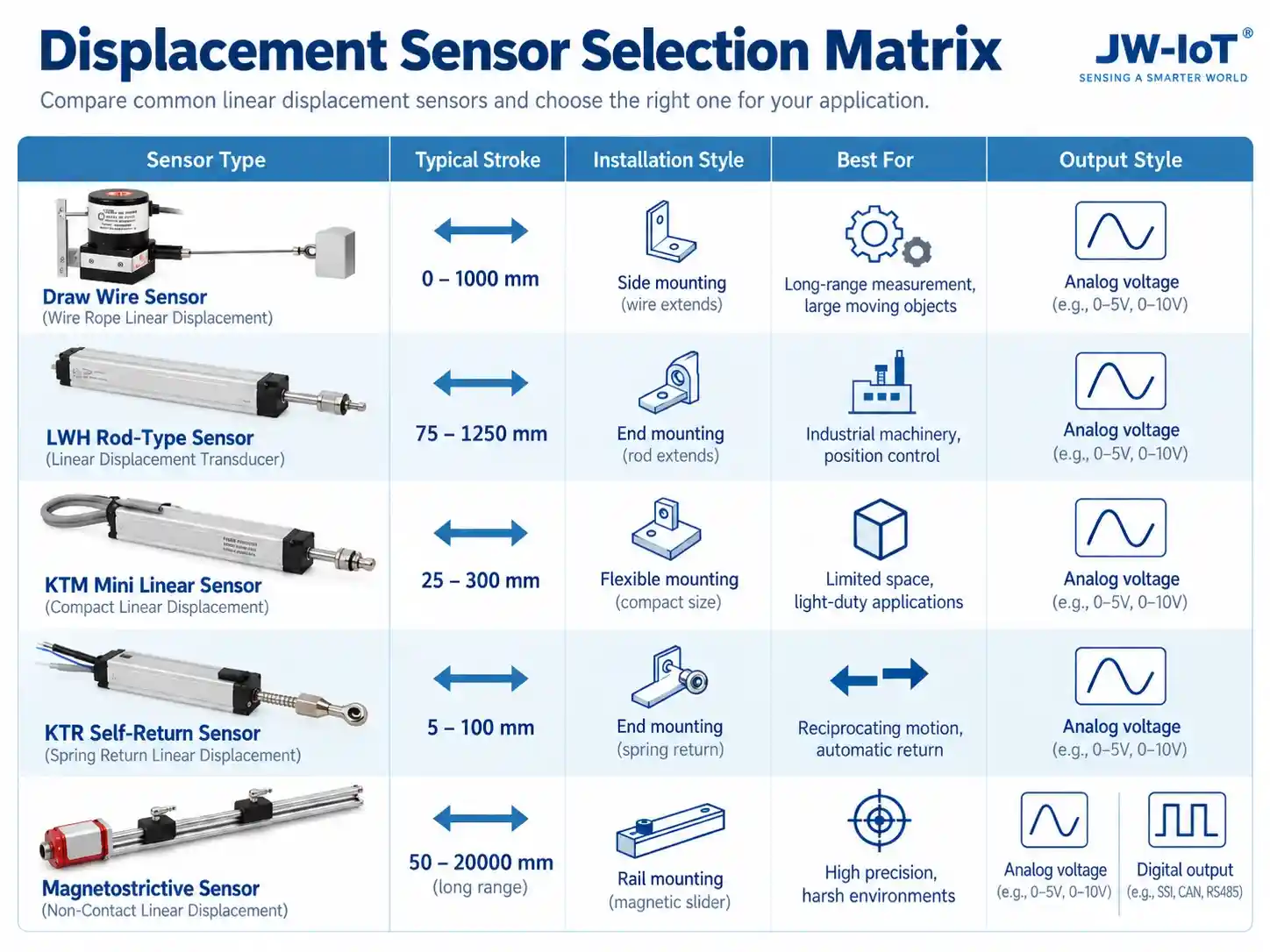
The following table summarizes the principal differences between common industrial linear displacement sensors.
| Technology | Measurement Mechanism | Position Feedback | Primary Selection Advantage |
| Draw Wire | Retractable Cable and Spool | Depends on Sensing Element | Compact Housing for Longer Travel |
| Linear Potentiometer | Moving Rod and Resistive Contact | Direct Analog Position | Mechanical Position Feedback |
| Spring Loaded Linear | Contact Shaft and Return Spring | Direct Analog Position | Intermittent Contact Measurement |
| Magnetostrictive | Moving Magnet and Waveguide | Absolute Position | Non-Contact Sensing |
| Incremental Encoder | Pulse Generation from Movement | Incremental Counts | Pulse-Based Motion Feedback |
There is no universally superior displacement sensor.
The correct choice depends on the complete measurement system rather than one specification.
For instance, a magnetostrictive sensor may be attractive for hydraulic cylinder integration, while a compact potentiometer may be more practical for a small packaging machine.
A draw-wire sensor may be preferable where a long rigid sensor body cannot be accommodated.
4. How to Understand Displacement Sensor Accuracy
Measurement performance is a critical part of sensor selection.
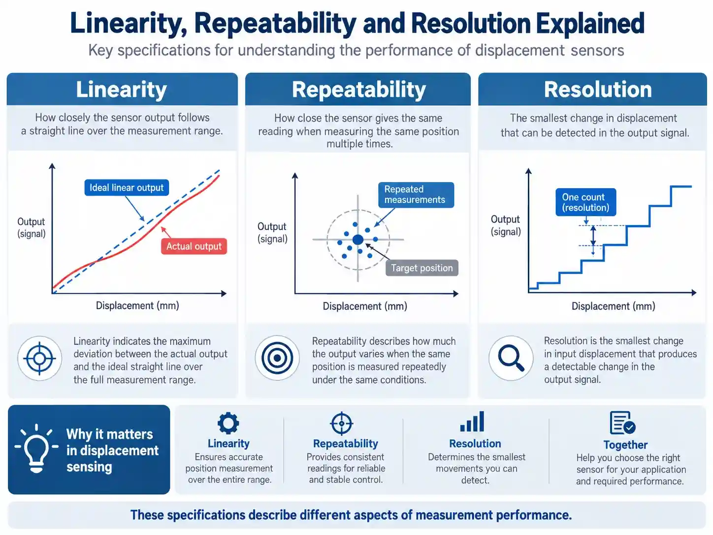
However, terms such as accuracy, linearity, repeatability, resolution, and hysteresis describe different characteristics.
4.1 Linearity
Linearity describes how closely the actual sensor response follows a defined reference line.
Manufacturers often express linearity as a percentage of full scale (%FS).
For example, a 1000mm sensor with a specified linearity of ±0.1%FS has a linearity deviation equivalent to ±1mm under the stated definition.
This is not necessarily the total measurement error.
4.2 Repeatability
Repeatability describes how consistently the measurement system produces results under specified repeated conditions.
A sensor may demonstrate excellent repeatability while still having a systematic offset or nonlinearity.
4.3 Resolution
Resolution describes the smallest change distinguishable by the sensor and measurement electronics.
For analog potentiometers, the sensing element can provide continuously varying output, but practical resolution depends on signal noise, electronic conversion, and the connected controller.
For incremental encoders, count resolution depends on the encoder and the mechanical conversion between spool rotation and cable travel.
4.4 Hysteresis
Hysteresis describes differences in output at the same position depending on the direction of approach.
Mechanical friction, sensing characteristics, and linkage conditions can contribute to hysteresis.
4.5 Measurement Uncertainty
The total measurement result may be influenced by:
- Sensor calibration
- Mechanical alignment
- Temperature variation
- Electrical noise
- Signal acquisition
- Mounting stability
- Reference-point movement
For additional guidance, the NIST Engineering Statistics Handbook discusses measurement process characterization and uncertainty evaluation.
Selection recommendation: Compare sensor performance using the same measurement definitions, range, and test conditions. Do not select a product based only on its smallest advertised resolution.
5. Industrial Applications of Displacement Sensors
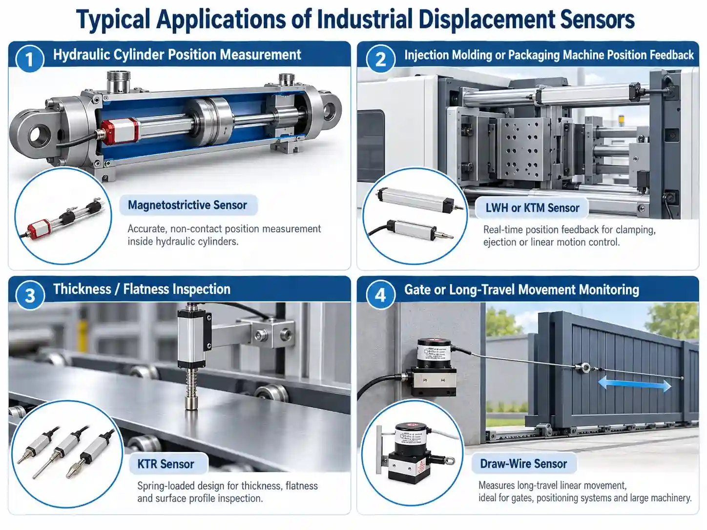
5.1 Hydraulic Cylinder Position Measurement
Hydraulic cylinders require position feedback for controlled mechanical movement and stroke monitoring.
Two common arrangements are:
Internal measurement: A compatible magnetostrictive probe can be integrated into a properly designed hydraulic cylinder assembly.
External measurement: A rod-type potentiometer or draw-wire sensor can measure cylinder-related movement through a suitable mechanical linkage.
The choice depends on cylinder construction, installation space, pressure conditions, expected stroke, and controller requirements.
For absolute internal position feedback, consider the JW-MDS(S09) Magnetostrictive Position Sensor.
5.2 Injection Molding and Packaging Machinery
Industrial manufacturing equipment uses linear displacement sensors for moving platens, slides, actuators, and positioning mechanisms.
Rod-type potentiometers are useful where mechanical movement can be directly connected to the measuring shaft.
A compact linear sensor may be preferred for shorter machine travel, while longer-stroke models are suitable for larger mechanical assemblies.
The KTM Mini Linear Sensor and LWH Rod-Type Sensor address different stroke and installation requirements.
5.3 Thickness and Flatness Inspection
Contact displacement measurement is used in inspection fixtures to detect relative height or thickness differences.
A spring-loaded sensor can press against a target surface and produce a position-related electrical signal.
However, a complete thickness or flatness measurement system requires an appropriate reference, measurement fixture, contact force, and calibration method.
For these applications, the KTR Self Return Sensor is an option to evaluate.
5.4 Gate Position Monitoring
Industrial gates, lifting mechanisms, and movable water-control structures may require continuous position feedback.
Draw-wire displacement sensors can measure relative movement between a fixed mounting point and the moving structure.
Outdoor applications require attention to cable protection, mounting stability, water exposure, temperature, and measurement travel.
5.5 Structural Relative Displacement Monitoring
Displacement measurements are also used in selected bridge joints, retaining structures, and infrastructure monitoring projects.
A sensor installed between two appropriate reference points can record movement along its measurement axis.
Such measurements should not be confused with an independent assessment of complete structural stability.
For integrated projects, explore the JW-IoT Structural Health Monitoring System.
6. How to Choose the Right Industrial Displacement Sensor
A practical selection process should begin with the mechanical measurement requirements.
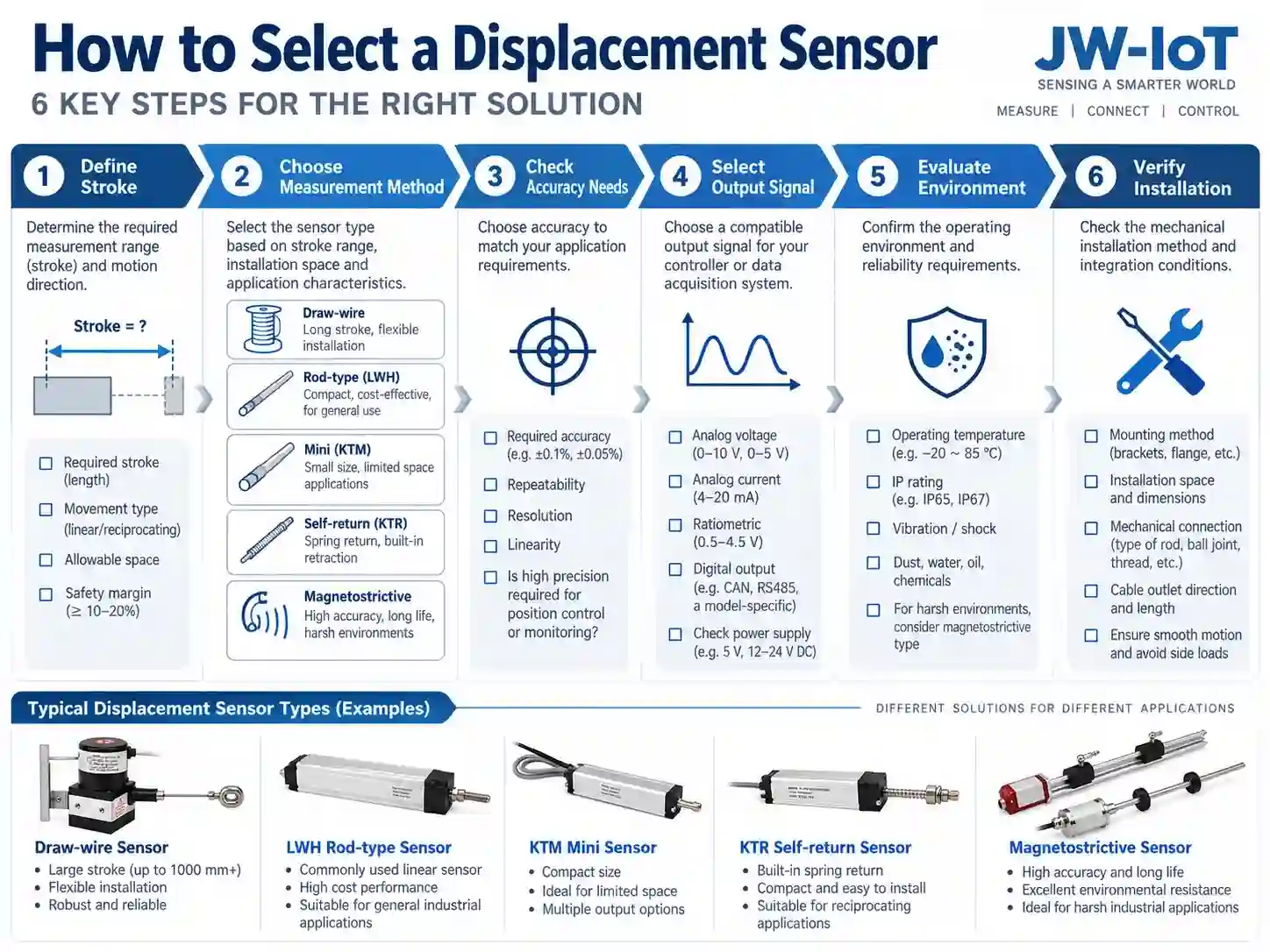
Step 1: Define the Measuring Stroke
Determine the minimum and maximum expected positions.
Allow for installation offsets, mechanical tolerances, and unexpected movement.
Avoid selecting a sensor whose maximum stroke is equal to the maximum expected machine travel without adequate margin.
Step 2: Identify the Measurement Method
Determine whether the application requires:
- Direct rod coupling
- Retractable cable measurement
- Spring-loaded contact
- Non-contact magnet position measurement
- Incremental pulse feedback
The installation geometry may eliminate unsuitable technologies before electrical specifications are considered.
Step 3: Define Measurement Performance
Establish requirements for linearity, repeatability, resolution, response time, and measurement uncertainty.
Select performance values appropriate to the actual application rather than automatically choosing the most demanding specifications.
Step 4: Choose the Output Interface
Common displacement sensor output options include:
| Output | Typical Receiving Equipment | Key Consideration |
| Resistance / Potentiometric | Compatible Measuring Circuit | Excitation and Loading |
| 0–5V / 0–10V | PLC Analog Voltage Input | Voltage Range and Noise |
| 4–20mA | PLC or RTU Current Input | Supply and Loop Compatibility |
| RS485 | Digital Controller or Gateway | Protocol and Communication Settings |
| SSI | Compatible Digital Interface | Timing and Electrical Compatibility |
| ABZ Encoder | High-Speed Counter | Pulse Rate and Position Referencing |
RS485 describes an electrical interface and does not automatically indicate Modbus RTU support.
Likewise, an analog output is not necessarily included in every variant of a sensor series.
Step 5: Evaluate the Operating Environment
Check the required:
- Operating temperature
- Protection rating
- Vibration tolerance
- Moisture resistance
- Chemical compatibility
- Mechanical service life
- Cable and connector protection
For example, IP65 does not mean a sensor can be continuously submerged.
Step 6: Verify Installation and Mechanical Life
Rod-type sensors require correct shaft alignment.
Draw-wire sensors require suitable cable routing and controlled retraction.
Spring-loaded sensors require appropriate contact force.
Magnetostrictive sensors require correct magnet positioning and compatible probe installation.
Mechanical installation is part of the measurement design, not merely a mounting detail.
Step 7: Consider the Complete Monitoring System
A displacement sensor normally provides the measurement signal. Data storage, remote transmission, visualization, and alarms are usually managed by connected equipment.
A typical system architecture is:
Displacement Sensor → Signal Acquisition / PLC / RTU → Industrial Monitoring Platform
For connected measurement projects, review JW-IoT Industrial IoT Monitoring Solutions.
7. Recommended JW-IoT Displacement Sensor Portfolio
The following overview helps identify an appropriate starting point for product selection.
| Product | Listed Measuring Range | Primary Application Direction |
| JW-KTR(S05) Self Return | 5–100mm | Contact Measurement |
| JW-KTM(S04) Mini Linear | 25–300mm | Compact Machinery |
| JW-LWM(S02) LWH Linear | 75–1250mm | Rod-Type Machine Stroke |
| JW-WPS-XS(S10) Draw Wire | 0–1000mm | Compact Cable Extension |
| JW-WPS-S(S11) Draw Wire | 0–2500mm | Medium-Stroke Cable Measurement |
| JW-MDS(S09) Magnetostrictive | 50–20000mm | Absolute Magnet Position |
| JW-IDW(S14) Incremental Draw Wire | 0–100000mm | Long-Travel Encoder Feedback |
The ranges above describe listed product-family options, not guaranteed availability of every intermediate stroke or output combination.
Final selection should be based on the specific datasheet and ordering configuration.
8. Common Mistakes When Selecting Displacement Sensors
One frequent mistake is selecting a sensor using measurement range alone.
Two sensors with overlapping stroke specifications may have very different installation requirements.
Other common mistakes include:
Confusing resolution with accuracy. A fine output resolution does not guarantee equivalent overall measurement accuracy.
Ignoring mechanical alignment. Excessive side loading can affect measurement quality and service life.
Selecting the wrong signal interface. A controller designed for voltage input cannot automatically read a current-loop or encoder output without suitable hardware.
Ignoring reference stability. In structural measurement, movement of the nominally fixed reference point can change the recorded relative displacement.
Assuming all options are standard. A sensor family may offer multiple outputs or materials, but individual versions can have different electrical and mechanical requirements.
Neglecting commissioning checks. Measurement scaling should be verified using known positions after installation.
9. Frequently Asked Questions
What is the difference between a displacement sensor and a position sensor?
A displacement sensor measures movement or changes in position. A position sensor reports an object’s location relative to a reference. Many industrial linear sensors can support both functions.
Which displacement sensor is suitable for long-stroke measurement?
Draw-wire systems and suitable magnetostrictive sensors can support long measuring strokes. The correct choice depends on mounting space, mechanical movement, output requirements, and environmental conditions.
What is the difference between a linear potentiometer and a magnetostrictive sensor?
A linear potentiometer uses a moving electrical contact along a resistive element. A magnetostrictive sensor uses a position magnet and waveguide-based measurement without sliding sensing contact.
Which sensor is suitable for thickness measurement?
A spring-loaded linear displacement sensor can be used in a properly designed contact measurement fixture. Measurement accuracy depends on fixture geometry, calibration, and contact conditions.
Can displacement sensors connect to a PLC?
Yes. Suitable analog, potentiometric, digital, or encoder configurations can connect to compatible PLC input modules.
What does absolute position measurement mean?
Absolute position measurement identifies position within a defined calibrated reference without relying solely on incremental pulse counting from an unknown starting point.
Are draw-wire displacement sensors suitable for outdoor use?
Some models are designed for industrial environmental protection. Actual outdoor suitability depends on enclosure rating, exposed cable conditions, mounting, temperature, and site requirements.
How do I choose between 4–20mA and RS485?
A 4–20mA output suits compatible analog current-input systems. RS485 supports digital communication but requires matching electrical and protocol configurations. Choose according to system architecture and controller compatibility.
10. Conclusion: Selecting the Right Displacement Measurement Technology
Selecting an industrial displacement sensor requires balancing measurement performance, stroke length, mechanical installation, environmental compatibility, and output requirements.
Draw-wire sensors provide flexible cable-based movement measurement. Linear potentiometers offer direct rod-type position feedback. Spring-loaded sensors support contact-based short-stroke measurement. Magnetostrictive sensors provide non-contact absolute position feedback, while incremental encoders support pulse-based motion measurement.
Rather than choosing a technology solely by its advertised precision or maximum range, engineers should evaluate how the sensor fits into the complete mechanical and control system.
JW-IoT offers multiple displacement sensing technologies for machinery automation, hydraulic equipment, industrial monitoring, and selected infrastructure applications.
Explore our Industrial Automatic Sensors or contact JW-IoT with your measuring stroke, output requirements, installation conditions, and project quantity for product selection assistance.