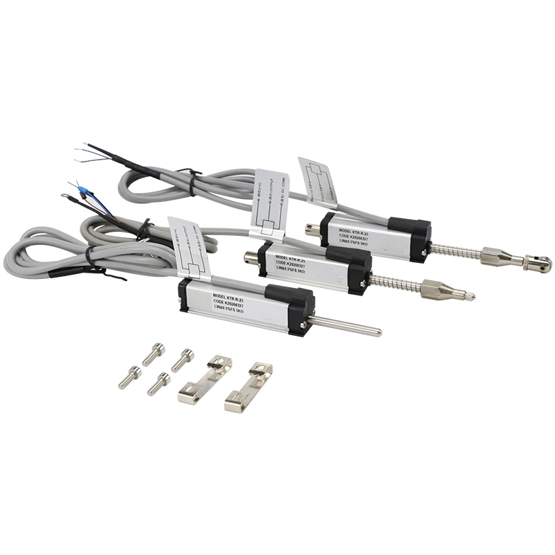
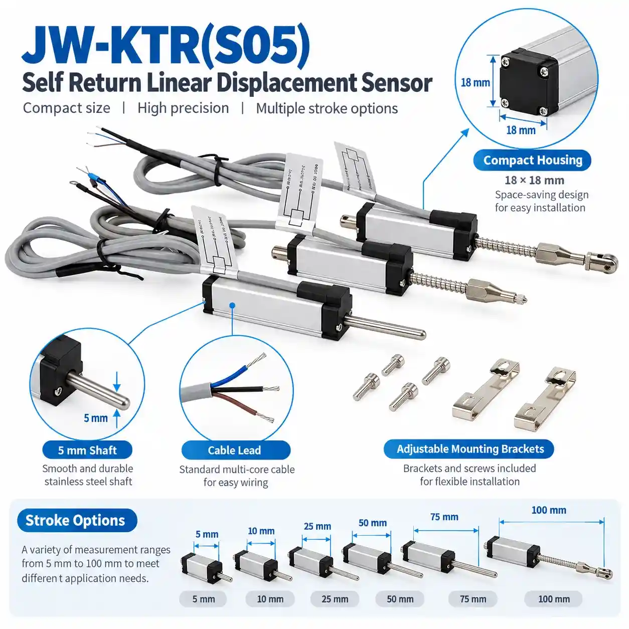
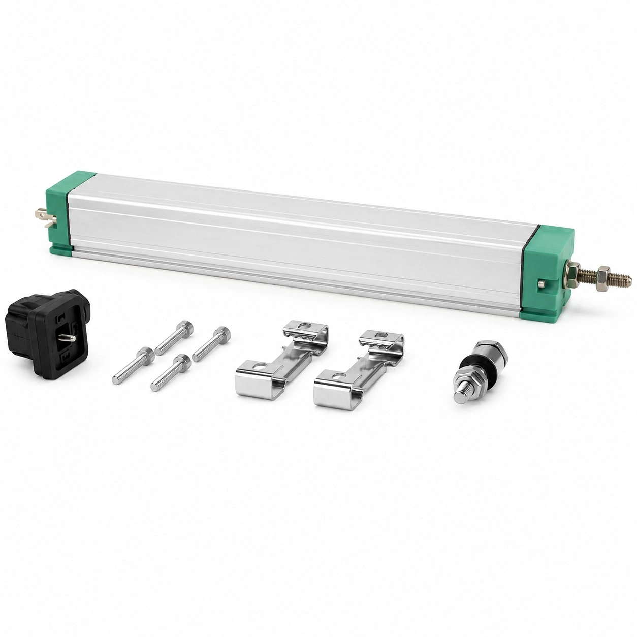
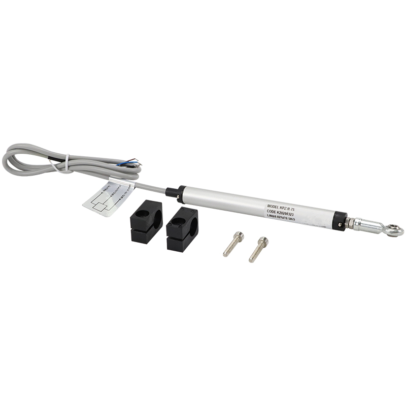
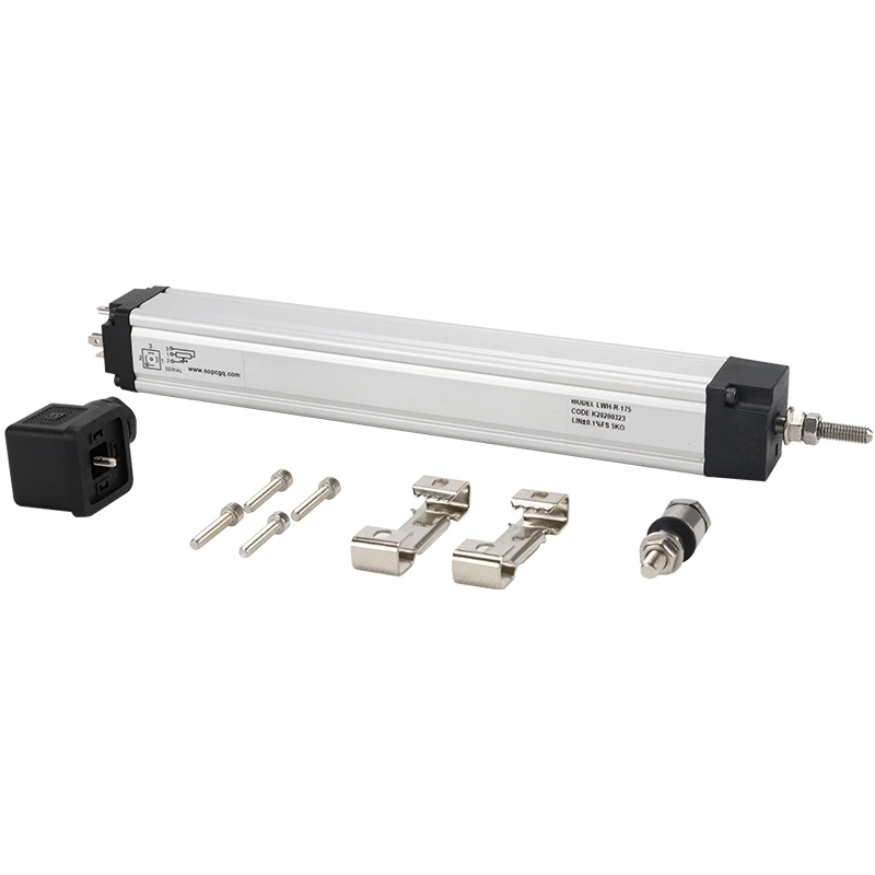
The JW-KTR(S05) Self Return Linear Displacement Sensor is a compact spring-loaded position transducer designed for short-stroke displacement measurement in industrial machinery and testing equipment.
Featuring a conductive plastic potentiometer, built-in return spring, stainless steel measuring shaft and anodized aluminum housing, the sensor converts linear contact movement into a proportional electrical signal.
With selectable measuring strokes from 5mm to 100mm, an 18 × 18mm housing profile and IP65 protection, the KTR sensor is suitable for thickness inspection, flatness measurement, compact machine positioning, mechanical testing and industrial automation.
Unlike conventional rod-type linear position sensors that require a mechanical connection to drive movement in both directions, the spring return displacement sensor can retract automatically after the applied contact force is released.
1. How Does a Self Return Linear Displacement Sensor Work?
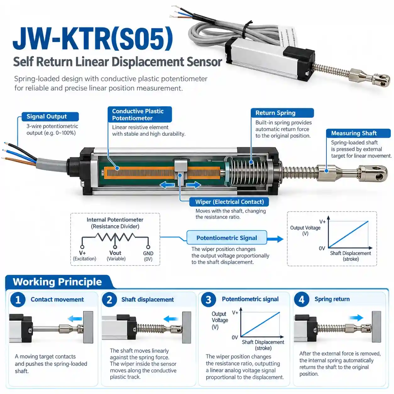
A spring loaded linear displacement sensor uses a measuring shaft, internal potentiometric sensing element and return spring.
When a moving object presses the measuring shaft, the shaft moves along the sensor’s measurement axis.
This movement changes the position of the internal sliding electrical contact along the conductive plastic resistive element.
The sensor produces an electrical signal corresponding to the shaft displacement.
When the external force is removed, the return spring moves the shaft back toward its initial position.
Contact Movement → Shaft Displacement → Potentiometric Signal → Spring Return
Why Use a Spring-Return Mechanism?
A conventional linear potentiometer generally requires mechanical coupling to drive its measuring rod.
The KTR self-return design is useful when the measurement involves intermittent contact, a moving surface or a short-travel mechanism where a fixed two-way mechanical linkage is impractical.
The spring-return structure is particularly relevant for:
Contact displacement inspection
Material thickness variation measurement
Surface height comparison
Mechanical fixture testing
Short-stroke machine movement monitoring
The available spring force and contact-tip geometry should be verified for applications involving delicate or deformable materials.
2. Technical Specifications
Parameter
Specification
Model
JW-KTR(S05)
Series
KTR
Sensor Type
Spring-Loaded Linear Potentiometer
Measuring Stroke
5–100mm
Measurement Principle
Conductive Plastic Potentiometer
Linearity
±0.05%, as listed in technical table
Repeatability
Less than 0.01mm
Resolution
Continuous Analog; Theoretical
Resistance Options
2kΩ / 5kΩ
Resistance Tolerance
±20%
Minimum Load Resistance
100kΩ
Listed Allowable Voltage
28V maximum
Electrical Connection
Direct Cable
Displacement Speed
Less than 3m/s
Mechanical Life
More than 50 Million Cycles
Housing Profile
18 × 18mm
Housing Material
Anodized Aluminum
Measuring Shaft
Stainless Steel
Shaft Diameter
5mm
Mounting
Adjustable Bracket
Protection Rating
IP65
Operating Temperature
-40°C to +80°C
Technical note: The product feature summary also references linearity up to 0.1%, depending on stroke. Confirm the applicable linearity specification for the selected model. The listed 28V maximum is not a universal supply requirement for optional output modules.
3. Output Signals and Controller Integration
3.1 Potentiometric Resistance Output
The standard KTR sensing element provides a position-dependent resistance or voltage-divider signal.
Available resistance values include:
2kΩ
5kΩ
A suitable receiving circuit is required to interpret the potentiometric signal.
3.2 Optional Analog Outputs
Signal-conditioning configurations may provide:
4–20mA
0–5V
0–10V
These signals can be connected to compatible PLCs, industrial controllers and data acquisition systems.
3.3 RS485 Output Option
RS485 is listed among the optional signal configurations.
Communication protocol support, electrical supply and interface documentation must be confirmed for the selected version.
Typical monitoring arrangement:
KTR Displacement Sensor → Signal Conditioning → PLC / Data Acquisition System → HMI
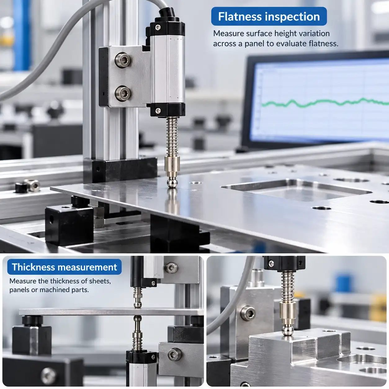
The self-return measuring shaft can be used to monitor relative surface height changes in suitable inspection fixtures.
As a target contacts the shaft, the sensor provides a displacement reading relative to its reference position.
A testing system may use this measurement to evaluate local height differences across a component.
4.2 Thickness Measurement
A spring-loaded linear displacement sensor can measure relative mechanical movement associated with material thickness in a properly designed measurement fixture.
Applications may include:
Sheet material thickness variation
Panel inspection
Mechanical clearance checks
Component dimensional testing
Measurement performance depends on fixture design, contact force, alignment and calibration.
4.3 Packaging and Printing Machinery
Packaging and printing equipment often contains short-travel mechanical assemblies.
The KTR sensor may be used for compact position feedback, contact displacement and selected machine adjustment measurements.
Its self-return structure can be useful where the monitored component contacts the measuring shaft during a machine cycle.
4.4 Valve and Small Mechanism Position Monitoring
Suitable valves and compact mechanical actuators may require short-stroke position monitoring.
The sensor can track shaft displacement where the return spring, contact geometry and mechanical forces are compatible with the application.
4.5 Industrial Testing and Automation Fixtures
The KTR series can support mechanical testing equipment, automated inspection stations and compact machine fixtures.
Applications should be evaluated according to required measuring stroke, repeatability, operating speed and environmental conditions.
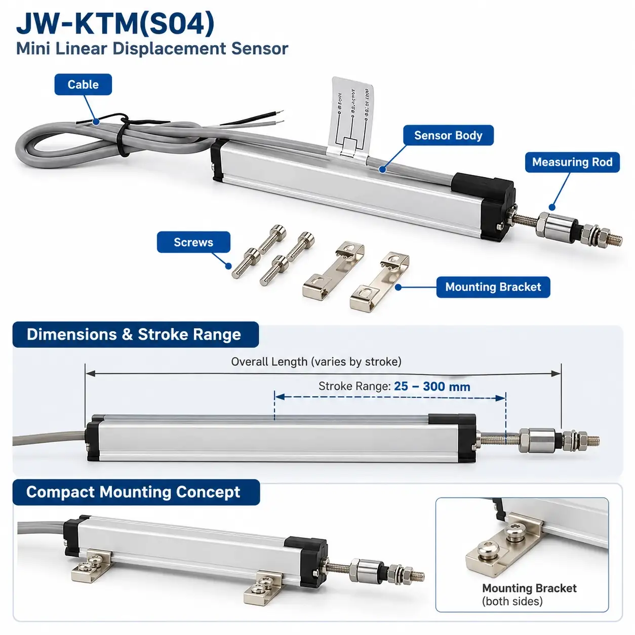
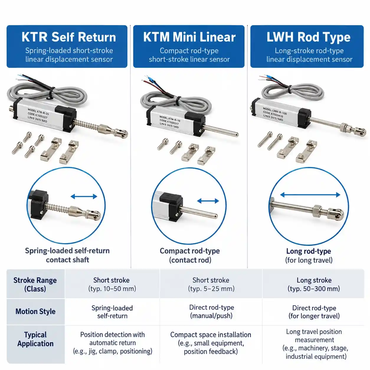
5. KTR Self Return vs KTM Mini Linear Sensors
Although both models use conductive plastic potentiometric sensing, their mechanical operation differs.
Feature
KTR Self Return
KTM Mini Linear
Measuring Stroke
5–100mm
25–300mm
Return Mechanism
Internal Spring
External Mechanical Movement
Measurement Method
Spring-Loaded Contact
Direct Rod Coupling
Main Advantage
Automatic Return
Compact Continuous Position Feedback
Typical Application
Thickness and Flatness Inspection
Machine Position Monitoring
Choose the KTR self-return sensor when the application benefits from spring-loaded contact measurement.
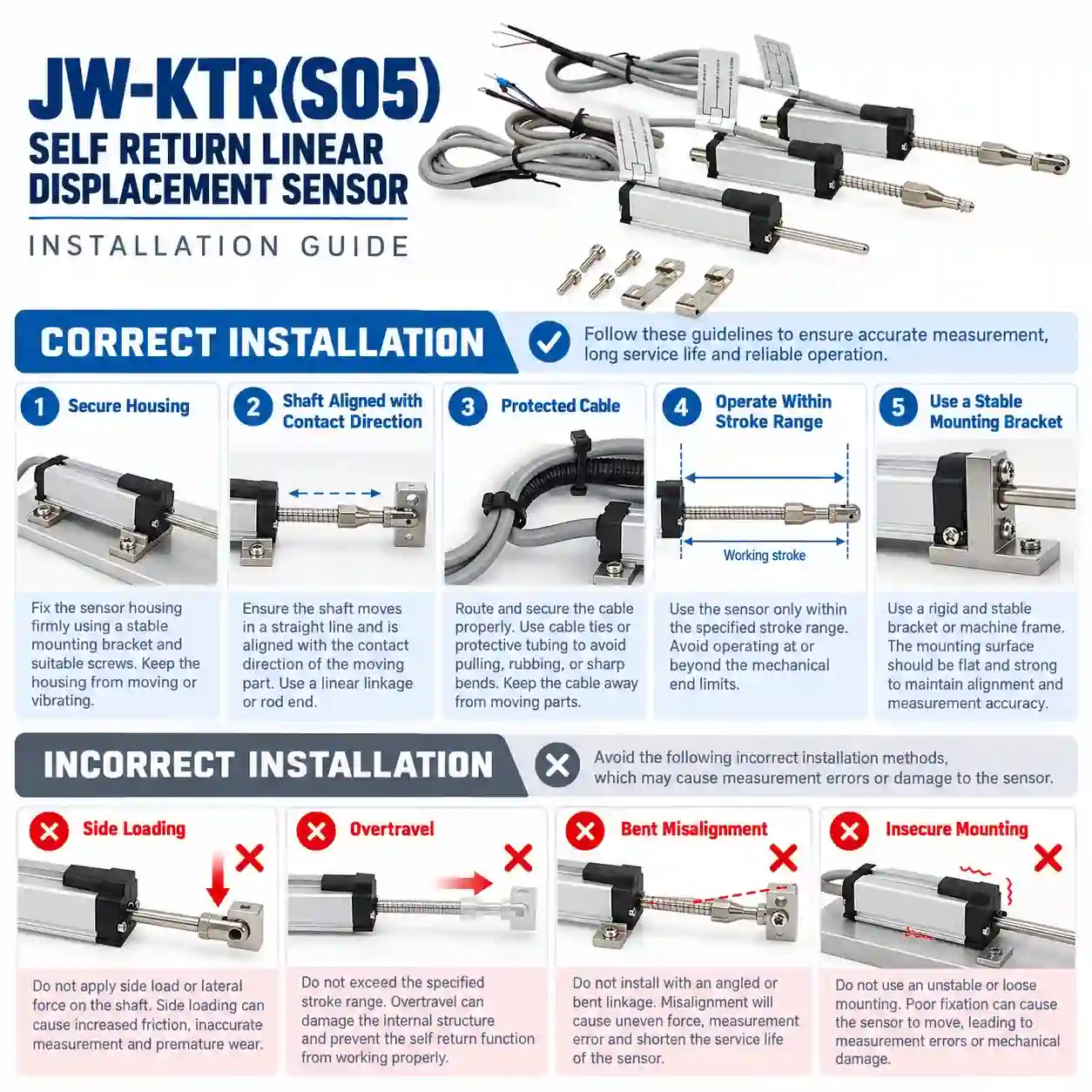
Mount the sensor on a stable machine frame using the appropriate adjustable bracket.
Avoid housing movement during measurement.
6.2 Align the Measuring Shaft
The contact movement should follow the shaft’s intended measurement axis.
Excessive side loading or bending may affect measurement consistency and accelerate mechanical wear.
6.3 Check Contact Force
Confirm that the return spring and contact arrangement are suitable for the measured component.
Avoid excessive loading of delicate surfaces.
6.4 Prevent Overtravel
Ensure the complete mechanical stroke remains within the selected sensor range.
Use suitable mechanical stops where required by the machine design.
6.5 Protect the Cable
Prevent cable pulling, sharp bending and contact with moving equipment.
6.6 Verify Output Scaling
Check the sensor response at known displacement positions before using the measurement in a control or testing system.
7. How to Select the Right Spring Loaded Sensor
Before ordering, confirm:
Required measuring stroke: Select a range between 5mm and 100mm.
Contact arrangement: Determine whether the target directly presses the shaft.
Return spring requirements: Verify contact force and recovery behavior.
Output signal: Select resistance, voltage, current or an available digital interface.
Measurement performance: Confirm linearity and repeatability for the selected stroke.
Mounting dimensions: Verify available space and fixture alignment.
Operating environment: Check temperature, dust, moisture and vibration conditions.
The correct sensor selection should account for both electrical performance and mechanical contact conditions.
8. Request Technical Specifications and Quotation
Looking for a spring loaded linear displacement sensor 5–100mm for contact measurement, thickness inspection or compact industrial machinery?
JW-IoT can assist with measuring stroke selection, output configuration and mechanical installation requirements.
Please provide your required stroke, application, output signal, installation conditions, contact-force requirements and purchase quantity.
Contact JW-IoT for technical specifications and quotation support.
FAQ
Q
1. What is a self return linear displacement sensor?
A
It is a linear position sensor with a built-in return spring that moves its measuring shaft toward the initial position when the external contact force is released.
Q
2. What is the measuring range of JW-KTR(S05)?
A
The product provides selectable measuring strokes from 5mm to 100mm.
Q
3. What is the difference between self-return and standard linear sensors?
A
A self-return sensor uses an internal spring for automatic shaft recovery. A conventional rod-type sensor generally depends on an external mechanical connection for movement.
Q
4. Is the KTR sensor suitable for thickness measurement?
A
Yes, in appropriately designed contact measurement fixtures where spring force, calibration and target geometry are suitable.
Q
5. What output signals are available?
A
Standard potentiometric resistance output is listed, with optional 4–20mA, 0–5V, 0–10V and RS485 configurations.
Q
6. Can the sensor connect to a PLC?
A
Yes. Compatible output configurations can be connected to an appropriate PLC input or signal-conditioning module.
Q
7. What is the protection rating?
A
The listed protection rating is IP65. This does not indicate suitability for immersion.
Q
8. How long is the mechanical service life?
A
The product documentation specifies more than 50 million operating cycles under applicable conditions.
 +86 13520127780
 info@jingelway.com