+86 13520127780
  info@jingelway.com








Floating PV Environmental Sensors Installation and Maintenance
Release time: 2026-08-28
Floating photovoltaic plants operate in an environment very different from conventional ground-mounted solar farms.
The PV modules may be exposed to high humidity, water-level variation, wind-driven movement, corrosion, condensation, wave action, and restricted maintenance access. These conditions not only affect the floating structures themselves but also influence how environmental sensors should be selected, positioned, installed, powered, and maintained.
For this reason, a reliable floating PV environmental monitoring system should not simply copy the weather station configuration used at a land-based solar farm.
Instead, the monitoring system should be designed around the actual reservoir, lake, pond, or water-body environment.
In this guide, we explain the key considerations for installing and maintaining floating PV environmental sensors, including weather sensors, water-level instruments, module temperature sensors, solar irradiance sensors, data loggers, communication equipment, and outdoor control enclosures.
What Are Floating PV Environmental Sensors?
Floating PV environmental sensors are instruments installed around a floating solar power plant to continuously measure meteorological, solar, thermal, and water-related conditions that may affect PV operation.
A typical floating solar monitoring system may measure:
- Solar irradiance
- PV module temperature
- Ambient air temperature
- Relative humidity
- Wind speed
- Wind direction
- Rainfall
- Atmospheric pressure
- Water level
- Water temperature
- Optional water-quality or site-specific environmental parameters
The sensors are normally connected to a data logger, RTU, IoT gateway, or monitoring station. Data can then be transmitted to a local SCADA system or cloud platform through RS485, Ethernet, 4G, LoRaWAN, or other communication technologies.
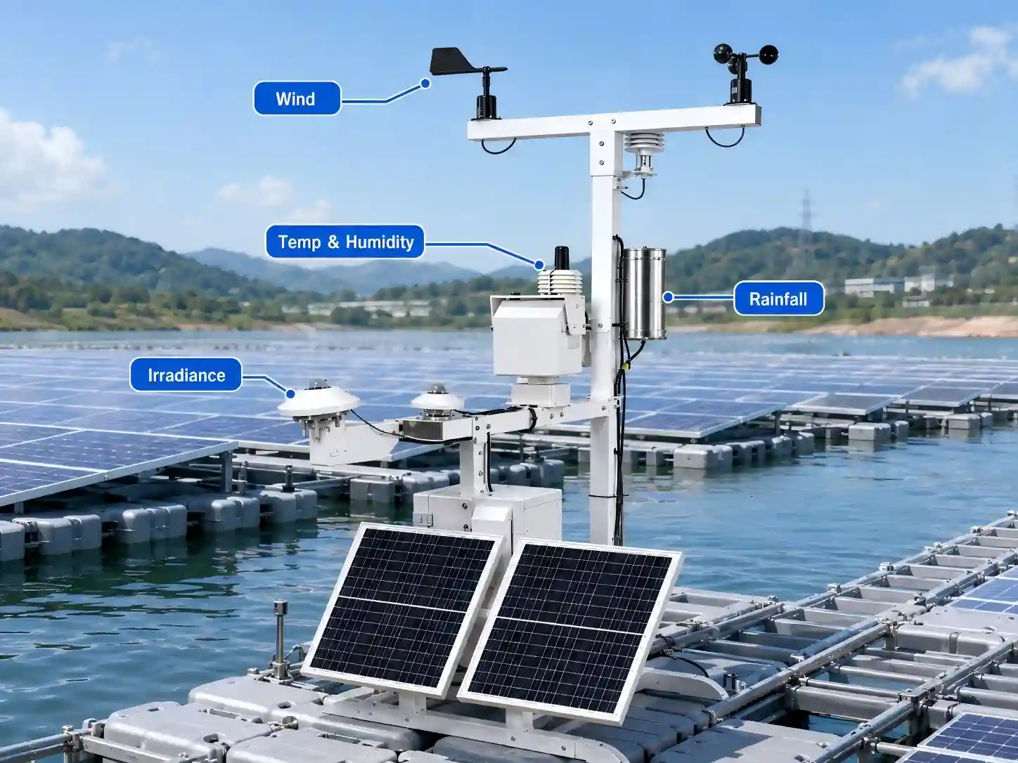
For a complete project-level architecture, see the JW-IoT Floating Solar Monitoring Station Solution.
1. Why Floating PV Plants Need Environmental Sensors
Environmental monitoring has two important roles in a floating PV project:
understanding PV performance and understanding the water-based operating environment.
Solar performance monitoring
PV output is strongly influenced by available solar radiation and module temperature.
By monitoring irradiance together with module temperature and electrical output, operators can better distinguish between changes caused by weather conditions and those associated with the PV system itself.
Typical measurements include:
- Global horizontal irradiance
- Plane-of-array irradiance
- Module backsheet temperature
- Ambient temperature
- Relative humidity
These variables provide useful environmental context for energy yield analysis, performance comparison, and long-term O&M.
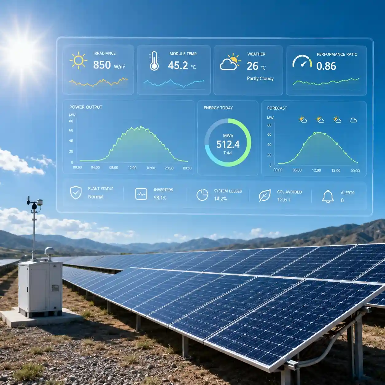
For broader photovoltaic meteorological monitoring, refer to the JW-IoT PV Plant Weather Station Solution.
Wind monitoring
Wind is particularly important for floating PV because floating arrays are installed on a moving water surface.
Strong wind may influence:
- Floating platform movement
- Mooring system loads
- Wave generation
- Equipment vibration
- Maintenance safety
- Module cooling
Wind speed and direction sensors therefore provide both meteorological information and operational context for floating solar sites.
Water-level monitoring
Reservoir and lake water levels may change due to rainfall, hydrological regulation, seasonal variation, irrigation demand, or hydropower operation.
Changing water levels can affect:
- Mooring geometry
- Access routes
- Cable management
- Floating-platform position
- Distance between monitoring equipment and the water surface
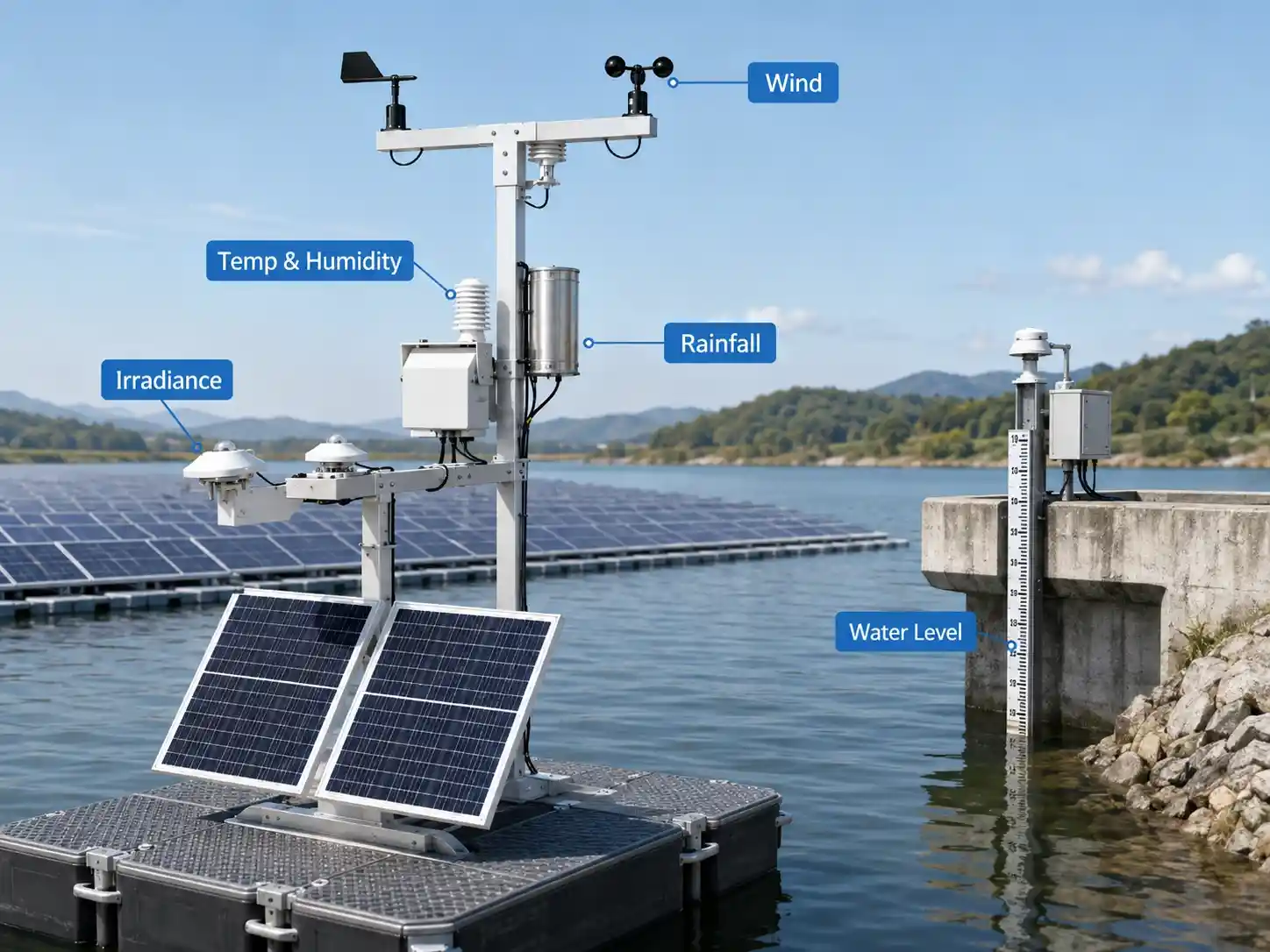
For projects with significant water-level variation, integrating a dedicated water level sensor into the monitoring system can provide an additional dataset for asset management.
JW-IoT provides non-contact radar instruments such as the Integrated Radar Water Level Gauge for Hydrology Station for reservoir, lake, river, and similar water-level monitoring applications.
2. Main Installation Challenges in Floating Solar Projects
Installing sensors on a floating PV plant introduces several challenges that are less significant at conventional ground-mounted sites.
High Humidity and Condensation
Equipment located above water may experience sustained high humidity.
Even when a sensor enclosure is weather-resistant, repeated temperature changes can encourage condensation around:
- Cable glands
- Junction boxes
- Communication terminals
- Connectors
- Data-logger enclosures
This means enclosure selection and cable entry design should be considered as carefully as sensor accuracy.
Corrosion
Metal components in floating solar environments can be continuously exposed to moisture.
Depending on water chemistry and local environmental conditions, corrosion may affect:
- Mounting brackets
- Screws
- Sensor housings
- Masts
- Junction boxes
- Cable supports
Where appropriate, corrosion-resistant materials and suitable protective treatments should be selected for long-term deployment.
Platform Movement
A floating platform is not a completely rigid foundation.
Wind and waves may cause:
- Tilting
- Rotation
- Vibration
- Relative movement between floating sections
This matters because some meteorological instruments require consistent orientation or leveling.
Solar irradiance sensors, for example, should be installed according to the measurement plane required by the project.
For professional PV irradiance monitoring, instruments such as a Class A Pyranometer Solar Radiation Sensor can be integrated into the monitoring architecture.
Limited Maintenance Access
A sensor installed in the middle of a floating array can be much more difficult to reach than one installed beside a ground-mounted PV row.
Maintenance may require:
- Boats
- Floating walkways
- Special safety procedures
- Temporary system shutdown
- Additional personnel
Therefore, ease of access should be considered before deciding exactly where each sensor is mounted.
A theoretically ideal measurement location may not always be the best operational location if routine inspection becomes impractical.
3. Where Should Floating PV Environmental Sensors Be Installed?
There is no universal sensor layout for every floating solar farm.
Locations should be determined according to plant size, float layout, prevailing wind, surrounding terrain, water-level variation, monitoring objectives, and applicable project requirements.
However, several general principles can help.
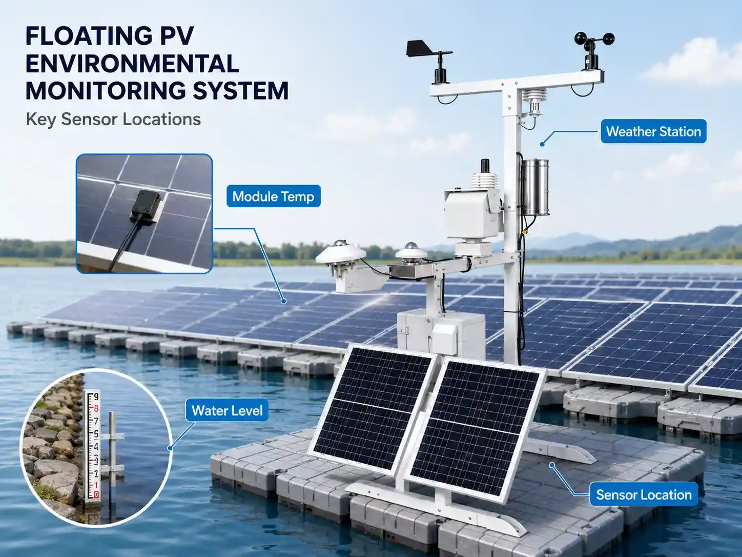
Solar Irradiance Sensors
Solar irradiance measurements should represent the solar conditions experienced by the PV array.
Depending on the monitoring objective, projects may use:
Global Horizontal Irradiance (GHI)
Measures solar radiation on a horizontal plane.
Plane-of-Array (POA) Irradiance
Measures irradiance on a plane aligned with the PV modules.
For PV performance evaluation, POA irradiance can be particularly useful because it better represents the radiation arriving at the module plane.
The sensor should remain free from unnecessary shading caused by:
- Masts
- Antennas
- PV frames
- Nearby structures
- Communication boxes
Where multiple floating arrays cover a large area, more than one measurement point may be considered when environmental conditions vary significantly across the site.
Learn more about Solar Irradiance Sensors for PV Monitoring.
PV Module Temperature Sensors
Module temperature sensors are typically attached to the rear surface of representative PV modules.
Installation should ensure:
- Good thermal contact
- Secure attachment
- Protection of the cable route
- Minimal influence from mounting materials
- Selection of a representative module
For large floating PV plants, multiple temperature measurement points can provide better information than relying on a single module.
This is especially useful when different areas have different:
- Array orientations
- Ventilation conditions
- Module technologies
- Irradiance exposure
Wind Speed and Direction Sensors
Wind instruments need an open measurement environment.
Avoid mounting them directly behind:
- PV modules
- Communication cabinets
- Structural frames
- Other large obstacles
Otherwise, local turbulence or shielding may distort the measurement.
Wind-direction sensors also require correct directional alignment during installation.
If the floating platform can rotate or significantly change orientation, the installation design should account for this before relying on conventional directional measurements.
Ambient Temperature and Humidity Sensors
Temperature and humidity sensors should measure ambient air rather than heat generated by nearby equipment.
They should therefore be positioned away from:
- Direct module heat
- Electrical cabinets
- Inverters
- Exhaust sources
- Surfaces with strong reflected heat
A suitable radiation shield should be used where required to reduce solar-heating effects on temperature measurement.
Water-Level Sensors
Water-level measurement is normally most practical from a stable reference structure rather than directly from a moving floating platform.
Possible installation points include:
- Reservoir banks
- Fixed piers
- Bridges
- Intake structures
- Fixed monitoring towers
Non-contact radar measurement can be attractive because the sensing instrument does not need to remain submerged.
The installation location should provide a clear measurement path to the water surface and avoid unnecessary obstructions.
4. Fixed Shore Station or Floating Monitoring Point?
One of the most important design decisions is whether the monitoring system should be installed on land, on a fixed structure, on the floating PV platform, or as a combination of these options.
In many projects, a hybrid architecture is practical.
| Monitoring Parameter | Typical Location |
| Solar irradiance | Near or within representative PV array |
| Module temperature | Directly on PV module |
| Wind speed/direction | Open monitoring mast |
| Ambient temperature/humidity | Ventilated, shielded location |
| Water level | Stable shore or fixed structure |
| Data logger/RTU | Protected enclosure |
| Gateway | Position selected for reliable network coverage |
A hybrid design allows sensors that must represent the PV array to remain close to the modules, while instruments requiring a fixed reference—such as some water-level measurements—can remain on shore.
This also reduces the number of electronic devices exposed directly to the floating environment.
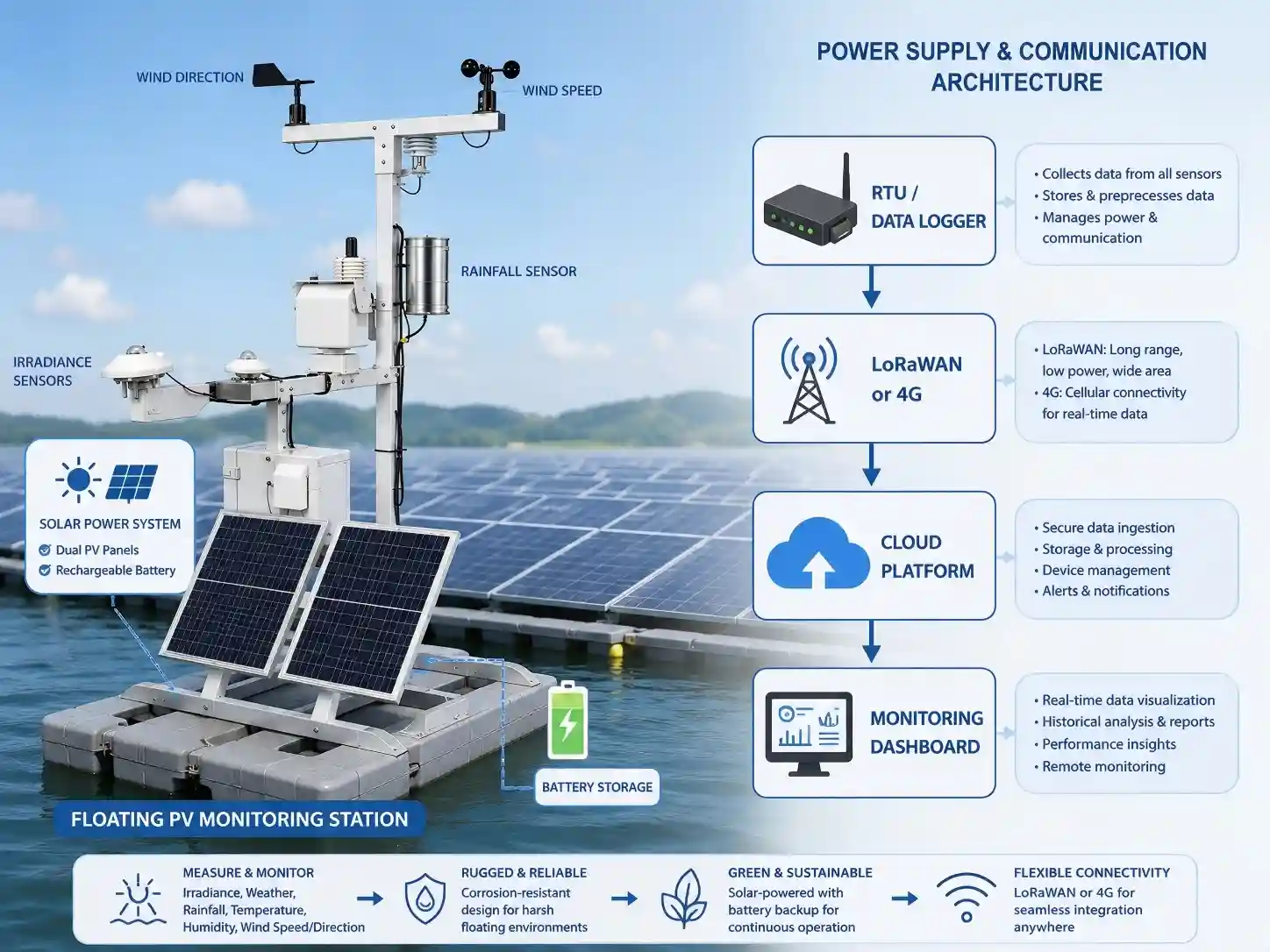
5. Power Supply Options for Floating PV Monitoring
Power architecture should be considered early during system design.
Environmental monitoring stations may use several approaches.
DC Power From the PV Site
Where a reliable auxiliary power source is available, monitoring equipment may be powered from the plant electrical system through appropriate power-conditioning equipment.
This can simplify continuous operation.
However, backup power should be considered according to the project requirements.
Independent Solar Power
Remote monitoring points may use a dedicated:
- Solar panel
- Charge controller
- Battery
- Outdoor power enclosure
Independent solar power can be particularly useful for:
- Water-level monitoring points
- Remote shoreline stations
- Communication gateways
- Environmental sensors away from the main electrical infrastructure
System sizing should be based on the total energy consumption of the monitoring system, not simply the sensor power rating.
The calculation should include:
- Sensors
- RTU/data logger
- Communication modem
- Gateway
- Heating or auxiliary equipment if used
- Transmission interval
- Battery autonomy requirement
6. Communication Options: RS485, 4G or LoRaWAN?
Floating PV monitoring systems often combine wired and wireless communication.
The correct architecture depends on plant size and existing infrastructure.
RS485 / Modbus
RS485 is widely used for connecting environmental sensors to a nearby data logger or RTU.
Advantages include:
- Simple sensor integration
- Multi-device bus architecture
- Common industrial protocol support
- Suitable for local data acquisition
However, long cable runs across moving floating structures require careful cable routing and mechanical protection.
4G LTE
4G is useful when the monitoring station needs to transmit data directly to a remote server or cloud platform.
It can be suitable for:
- Remote reservoirs
- Independent monitoring stations
- Shore-based gateways
- Sites without existing Ethernet infrastructure
Actual performance depends on local cellular coverage.
LoRaWAN
LoRaWAN can be considered when multiple monitoring points are distributed across a large floating solar project.
A typical architecture may look like:
Environmental Sensors → LoRaWAN Nodes → LoRaWAN Gateway → 4G/Ethernet → Cloud Platform
This can help reduce extensive communication cabling between geographically separated monitoring points.
However, gateway position, antenna height, obstacles, radio environment, and local regulations should be evaluated during project design.
7. Protecting Outdoor Electronics in Humid Environments
The sensor itself is only one part of the monitoring system.
Many field failures occur around:
- Connectors
- Cable entries
- Junction boxes
- Power terminals
- Communication devices
For floating PV applications, outdoor enclosures should therefore be selected according to actual environmental exposure.
Important design considerations include:
Appropriate enclosure protection
Select outdoor-rated cabinets and sensor housings appropriate for the installation conditions.
Cable glands
Cable entries should be correctly sized and tightened. Unused cable entries should be sealed.
Drip loops
Where appropriate, cables should be routed to reduce the chance of water running directly toward cable glands.
Corrosion-resistant components
Fasteners, brackets, and mounting structures should be selected according to environmental conditions.
Cable strain relief
Cable movement should not continuously transfer mechanical force to connectors or sensor terminals.
This is especially important where floating structures move relative to fixed infrastructure.
8. Maintenance Considerations for Floating PV Environmental Sensors
Floating PV monitoring equipment should be included in the plant’s preventive maintenance program.
Waiting until sensor data disappears completely often increases maintenance costs.
A practical inspection program can include the following.
Inspect Solar Radiation Sensors
Check for:
- Dust
- Bird droppings
- Water deposits
- Biological contamination
- Physical obstruction
- Incorrect leveling
Dirty optical surfaces can influence irradiance measurements.
Cleaning procedures should follow the sensor manufacturer’s recommendations.
Inspect Wind Sensors
Confirm that:
- Moving parts rotate normally where applicable
- The sensor is not obstructed
- Mounting remains secure
- Directional alignment remains correct
- Cables remain undamaged
After severe weather, wind instruments deserve additional inspection.
Check Module Temperature Sensor Attachment
Repeated temperature cycles and humidity can affect sensor adhesion or mounting.
Verify that the temperature probe remains securely attached to the intended measurement position.
Inspect Cable Routes
Look for:
- Excessive tension
- Loose cables
- Abrasion
- UV damage
- Connector movement
- Water ingress
Floating systems may experience continuous small movements, so cable management is particularly important.
Inspect Outdoor Enclosures
Check:
- Door seals
- Cable glands
- Internal condensation
- Corrosion
- Power terminals
- Surge-protection devices
- Communication equipment
A cabinet that looks intact externally can still develop moisture problems internally.
Validate Sensor Data
Maintenance should not rely only on visual inspection.
Historical data can help identify sensor issues.
Potential warning signs include:
- Sudden fixed values
- Impossible measurements
- Persistent zero readings
- Unexpected step changes
- Increasing differences between nearby sensors
- Long communication gaps
A monitoring platform can therefore act as an additional maintenance tool by helping operators detect abnormal data before a complete sensor failure occurs.
9. Recommended Floating PV Environmental Sensor Package
A monitoring package should be configured according to project objectives rather than selecting the maximum number of available sensors.
For a typical floating PV installation, a practical configuration may include:
Solar Monitoring
- Pyranometer or solar irradiance sensor
- Plane-of-array irradiance measurement
- PV module temperature sensor
Meteorological Monitoring
- Ambient temperature sensor
- Relative humidity sensor
- Wind speed sensor
- Wind direction sensor
- Optional rainfall sensor
- Optional atmospheric pressure sensor
Water Environment Monitoring
- Radar water level sensor
- Optional water temperature sensor
- Additional water-quality sensors where required by the project
Data Acquisition
- RS485/Modbus data logger or RTU
- Local data storage
- Edge communication terminal
Communication
- 4G LTE for remote connectivity
- LoRaWAN for distributed monitoring points
- Ethernet where fixed network infrastructure is available
Power
- Plant auxiliary DC power where available
- Independent solar panel and battery for remote monitoring points
Platform
- Real-time data visualization
- Historical trends
- Alarm configuration
- Multi-site management
- API or protocol integration with third-party systems
The final sensor package should always be adjusted according to:
plant size + monitoring objectives + site environment + communications + power availability + local project standards.
10. Example Floating Solar Monitoring Architecture
A typical floating PV environmental monitoring architecture can be divided into four layers.
Field Layer
Environmental instruments collect:
- Irradiance
- Module temperature
- Air temperature
- Humidity
- Wind
- Rainfall
- Water level
Data Acquisition Layer
A data logger or RTU collects sensor signals through interfaces such as RS485/Modbus.
Communication Layer
Monitoring data is transferred through:
- LoRaWAN
- 4G
- Ethernet
- Other project-specific communication networks
Platform Layer
The monitoring platform can provide:
- Real-time measurements
- Trend visualization
- Alarm management
- Historical data
- Multi-station comparison
- API integration
For broader PV monitoring architecture, see the JW-IoT Solar PV Monitoring System with IoT Automation.
11. Common Floating PV Sensor Installation Mistakes
Several avoidable mistakes can reduce the value of environmental monitoring data.
Mistake 1: Installing the wind sensor behind PV modules
PV arrays can create turbulence and shielding, resulting in measurements that may not represent the surrounding wind environment.
Mistake 2: Allowing structures to shade the irradiance sensor
Even temporary shading can influence solar radiation data.
Mistake 3: Installing all instruments on a moving platform
Some parameters are better measured from a stable reference point. Water level is a good example.
Mistake 4: Ignoring cable movement
Cables crossing moving structures need mechanical protection and suitable slack.
Mistake 5: Selecting communication technology without a site survey
A radio or cellular solution should be based on actual coverage conditions rather than assumptions.
Mistake 6: Designing for installation but not maintenance
Sensors should remain accessible for cleaning, inspection, calibration, and replacement.
Mistake 7: Treating enclosure protection as secondary
In humid water environments, reliable cable entries and junction boxes can be just as important as the sensors themselves.
12. How Often Should Floating PV Sensors Be Maintained?
There is no single maintenance interval suitable for every floating solar plant.
Inspection frequency depends on:
- Local humidity
- Rainfall
- Dust
- Bird activity
- Water chemistry
- Wind conditions
- Sensor type
- Accessibility
- Manufacturer recommendations
A better approach is to combine scheduled inspection with data-based condition monitoring.
For example, operators can perform regular physical inspections while also using historical monitoring data to identify abnormal drift, missing data, or differences between nearby sensors.
After extreme wind, storms, flooding, or unusual water-level changes, additional inspection may be appropriate.
FAQ
1. What environmental sensors are typically used in floating solar PV plants?
Floating PV plants may use solar irradiance sensors, module temperature sensors, ambient temperature and humidity sensors, wind speed and direction sensors, rainfall sensors, atmospheric pressure sensors, and water-level sensors. The exact configuration depends on the monitoring objectives and site conditions.
2. Why is water-level monitoring important for floating PV?
Water-level variation can influence floating-platform position, mooring geometry, access conditions, cable routing, and shoreline infrastructure. Monitoring water level provides useful environmental information for reservoir and lake-based floating PV projects.
3. Where should a water-level sensor be installed at a floating solar plant?
Where possible, water-level instruments should use a stable reference location such as a reservoir bank, pier, bridge, intake structure, or fixed monitoring platform. Non-contact radar sensors can measure the water surface without requiring continuous sensor immersion.
4. Can LoRaWAN be used for floating solar monitoring?
Yes. LoRaWAN can be considered for distributed environmental monitoring points where long communication cables are undesirable. The actual design should consider gateway location, radio coverage, antenna installation, local frequency regulations, and site layout.
5. Can floating PV sensors transmit data through 4G?
Yes. Where cellular coverage is available, a 4G RTU or gateway can transmit monitoring data from the site to a remote server or cloud platform.
6. How can floating solar sensors be protected from humidity?
Protection should consider outdoor-rated sensor housings and cabinets, properly sealed cable glands, suitable connectors, corrosion-resistant mounting materials, cable strain relief, and periodic inspection for condensation or water ingress.
7. Should floating PV plants use the same weather station as ground-mounted solar farms?
Not necessarily. Many measurement parameters are similar, but floating projects have additional installation considerations such as humidity, corrosion, platform movement, water-level variation, cable movement, and difficult maintenance access. The system should therefore be adapted to the specific site.
8. How does JW-IoT configure floating PV environmental monitoring systems?
JW-IoT can combine solar irradiance, module temperature, weather, water-level, data acquisition, LoRaWAN/4G communication, and remote monitoring components according to the project’s measurement parameters, number of monitoring points, power conditions, communication environment, and integration requirements.
Build a Monitoring Package Around Your Floating PV Site
A floating solar monitoring system should be designed as a complete field architecture rather than a collection of independent sensors.
The most suitable configuration depends on:
- What parameters need to be measured
- Where sensors can be installed
- How much the water level changes
- Whether monitoring points are fixed or floating
- Available power sources
- Communication coverage
- Number of monitoring locations
- Required platform or API integration
- Local environmental conditions
JW-IoT provides configurable environmental sensing, data acquisition, wireless communication, and IoT monitoring solutions for floating solar and other renewable-energy projects.
Request Floating PV Sensor Package
Send us your project information, including the plant size, water-body type, required monitoring parameters, number of monitoring points, communication method, and platform requirements, and our team can help prepare a preliminary sensor and system configuration.
→ Explore the JW-IoT Floating Solar Monitoring Station Solution
→ Explore the JW-IoT PV Plant Weather Station Solution