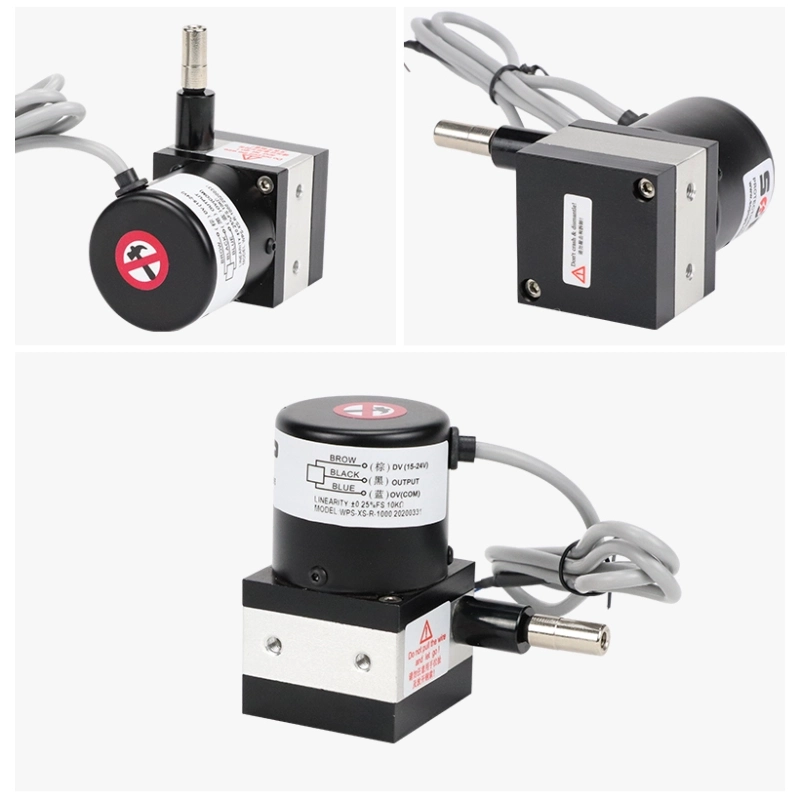
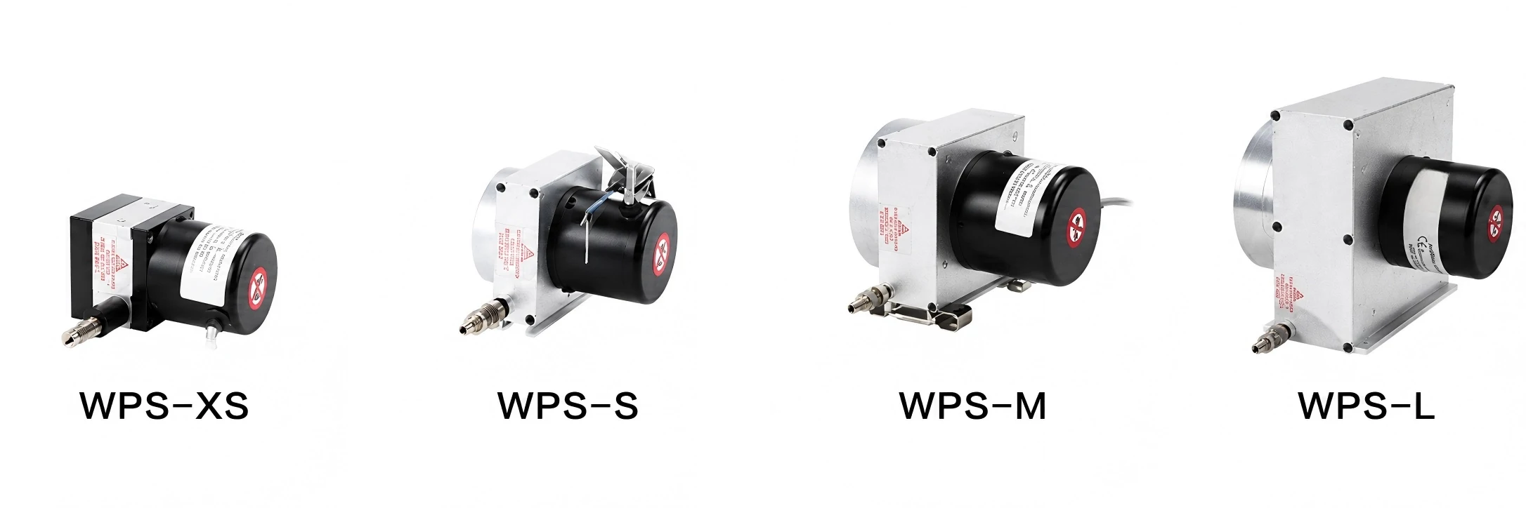
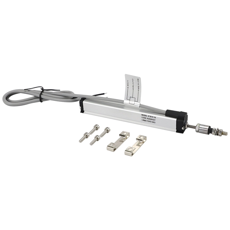
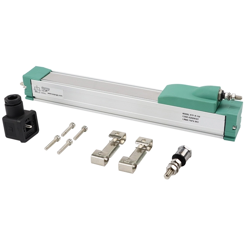
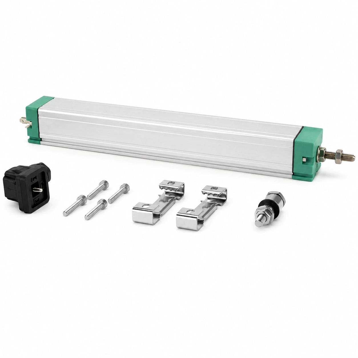
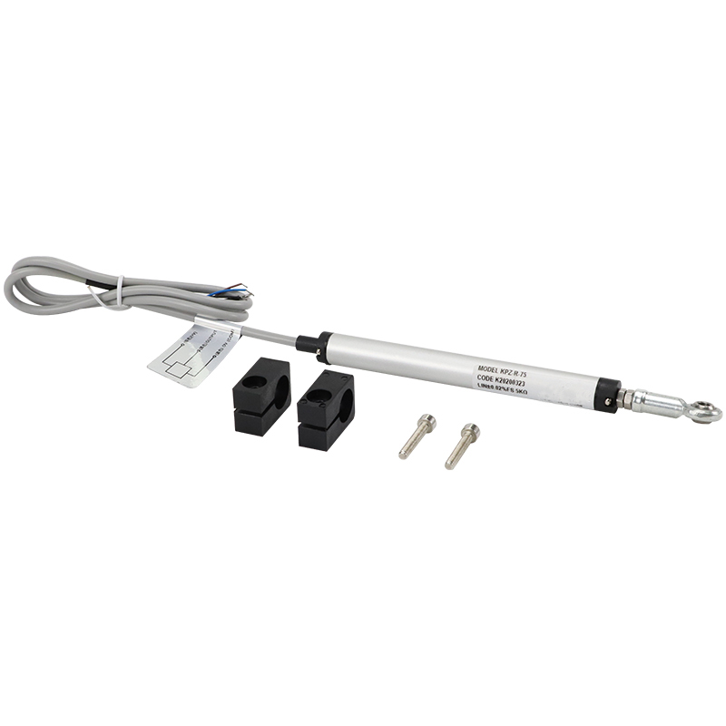
The JW-WPS-XS(S10) Draw Wire Displacement Sensor is designed for continuous linear position and displacement measurement over a range of 0 to 1000 mm.
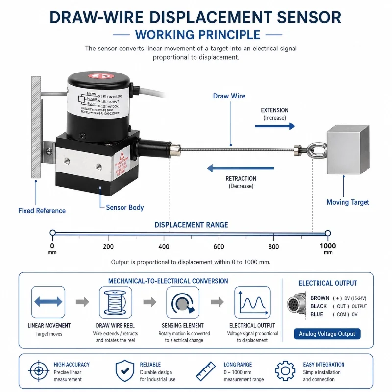
The sensor uses a retractable measuring cable to track the relative movement between a fixed point and a moving object. As the cable extends or retracts, the internal sensing mechanism converts the mechanical movement into a proportional electrical signal.
Its compact structure makes it suitable for applications where the expected movement is greater than the practical range of many short-stroke contact sensors, but installation space does not justify a large long-range displacement device.
Typical applications include:
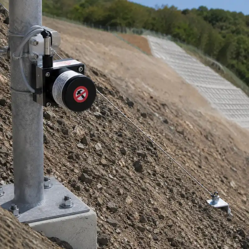
Slope surface displacement
Retaining-wall movement
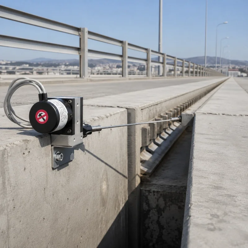
Bridge-joint displacement
Dam and embankment deformation
Tunnel convergence
Building crack or joint movement
Hydraulic gate position
Industrial machinery position
Lifting and telescopic equipment
Remote structural monitoring
The sensor can be connected to a compatible PLC, data logger, RTU or IoT monitoring terminal according to the selected output configuration.
What Is a Draw Wire Displacement Sensor?
A draw wire displacement sensor, also known as a cable-extension sensor, string potentiometer or wire-rope displacement sensor, measures linear movement by using a retractable cable.
The sensor body is installed on a stable reference point. The end of the measuring cable is attached to the moving object.
When the object moves:
The cable extends or retracts.
The internal spool rotates.
The sensing element converts the spool movement into an electrical output.
A PLC, data logger or RTU records the corresponding displacement.
Monitoring software displays real-time values and historical trends.
The sensor is especially useful when the distance between the fixed and moving points is too large for a short-stroke contact displacement sensor.
What Does the 0–1000 mm Range Mean?
The 0–1000 mm range means the measuring cable can monitor up to approximately one metre of linear extension within the specified operating range.
The selected range should not be exactly equal to the expected maximum movement.
A practical project should normally reserve additional travel for:
Installation tolerance
Initial cable extension
Unexpected movement
Seasonal expansion and contraction
Construction deviation
Emergency deformation
Maintenance adjustment
For example, a project expecting up to 700 or 800 mm of movement may be suitable for a 1000 mm sensor, subject to the required installation preload and safety margin.
If the expected movement could exceed the available range, select a longer-range model rather than operating the sensor near its mechanical limit.
The collected trend can help engineers evaluate whether movement is stable, progressive or event-related.
Bridge-Joint Displacement
The sensor can monitor relative movement across:
Expansion joints
Bearings
Deck sections
Structural gaps
Movable components
The measuring range should be selected according to thermal movement, traffic-related movement and expected structural displacement.
Dam and Embankment Monitoring
Potential applications include:
Joint opening
Gallery movement
Gate position
Embankment settlement-related displacement
Relative movement between concrete sections
Deformation around hydraulic structures
Installation should consider humidity, condensation, corrosion and flood exposure.
Tunnel Convergence Monitoring
The cable can be installed between selected reference points to monitor changes in tunnel width or structural opening.
Possible locations include:
Tunnel sidewalls
Roof-to-floor distance
Excavation sections
Temporary support
Underground mine roadways
Construction monitoring sections
Final sensor placement should follow the approved monitoring design.
Building and Foundation-Pit Monitoring
The sensor may be used for:
Structural-joint movement
Foundation-pit retaining-wall displacement
Temporary support movement
Construction settlement-related displacement
Large crack or gap monitoring
Adjacent-building movement
Industrial Machinery Position Monitoring
The sensor can measure:
Sliding-platform position
Telescopic movement
Lifting height
Hydraulic-cylinder movement
Door or gate position
Crane and hoist movement
Material-handling equipment
Test-machine travel
The selected cable speed, acceleration and cycle life must match the machine movement.
Hydraulic Gate Position
The measuring cable can track gate or actuator movement and provide position data to a controller or monitoring system.
For wet environments, verify:
Enclosure protection
Cable material
Connector sealing
Corrosion resistance
Drainage
Condensation protection
Technical Specifications
Keep the original verified parameter table on the page.
The following summary can be placed immediately above it:
Item
Specification
Series Type
WPS-XS
Measuring Range
0–1000 mm customizable according to customer requirements
Linearity Accuracy
Standard type 0.25%FS precision type 0.05%–0.08%FS
Repeatability
0.01%FS–0.005%FS
Output Type
Current voltage resistance pulse digital output
Current Output
4–20 mA or 20–4 mA
Voltage Output
0–10 VDC or 10–0 VDC
Resistance Output
0–5 kΩ or 0–10 kΩ
Pulse Output
Normally 3600–5000 PPR incremental encoder output AB phase or ABZ phase
Digital Output
RS485 signal or absolute encoder signal such as 4–20 mA 0–10 V CANopen Profinet
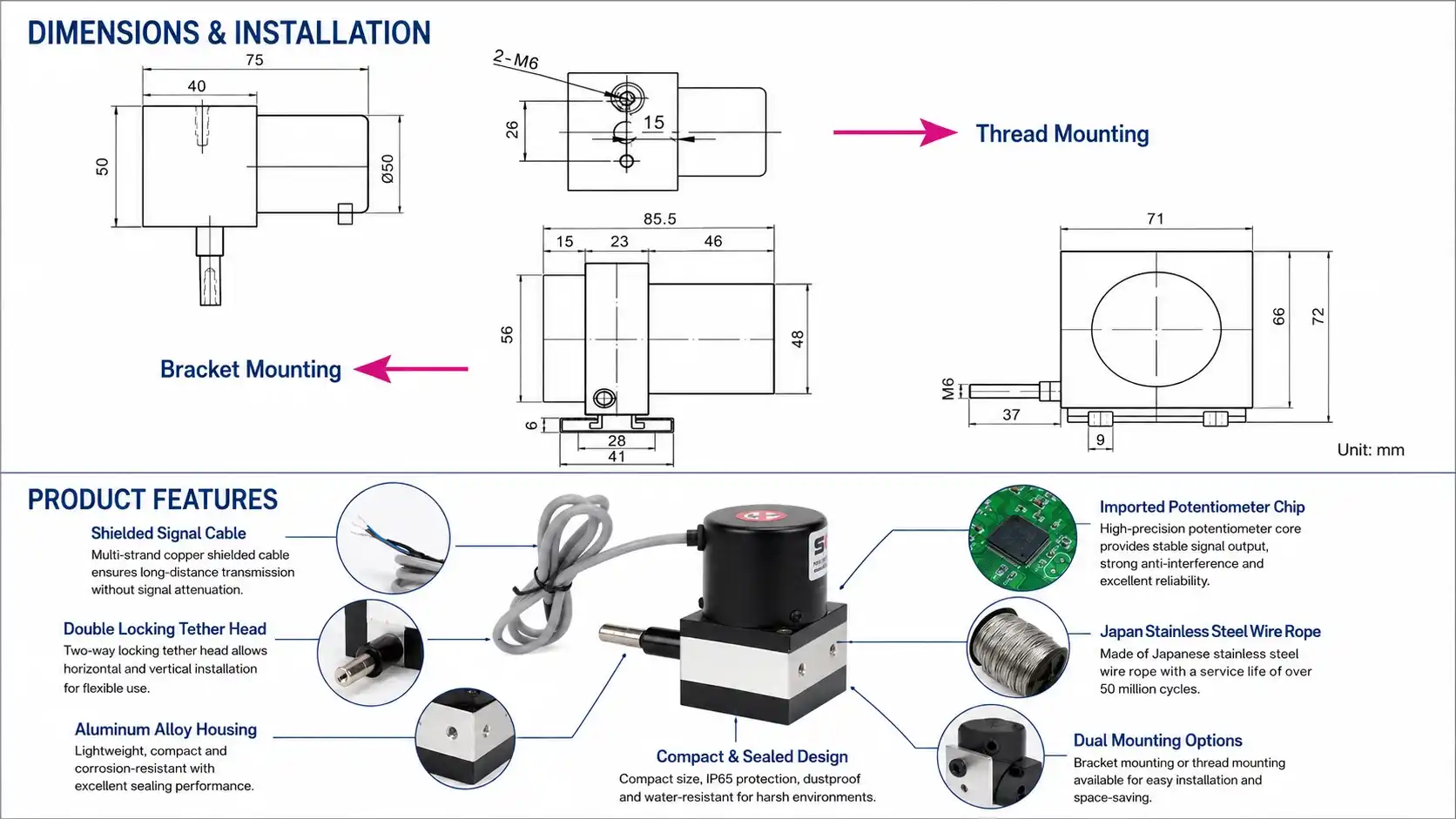
Fixing Screw
M4 mm
Installation Method
Bracket mounting or threaded mounting
Service Life
5 million reciprocating cycles
Protection Rating
IP65
Supply Voltage
24 VDC
Pulse Type Supply Voltage
5–24 VDC
Product Body Material
Aluminum alloy
Mounting Bracket Hole Distance
28 ±0.5 mm
Distance Between Two Brackets
Recommended 40–55 mm
Mounting Screw
M4
Tether Head Thread Mounting
M6
Do not replace the current verified values for accuracy, resolution, repeatability, cable tension, output, supply voltage, protection rating, operating temperature or cable material with unconfirmed data.
Available Output Options
The available electrical output should follow the ordered product configuration.
Common project requirements may include:
Resistance output
Voltage output
Current output
RS485 digital output
Incremental pulse or encoder output
Not every option is necessarily available for every mechanical range.
Before ordering, confirm:
Output type
Output range
Supply voltage
Wiring definition
Cable length
Connector type
Sampling frequency
Receiving-device input
Scaling formula
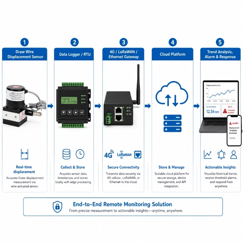
RS485 and Remote IoT Monitoring
When a compatible digital or signal-conversion configuration is used, the sensor can be integrated into a remote deformation-monitoring system.
A typical architecture is:
Draw Wire Displacement Sensor
→ Data Logger or RTU
→ LoRaWAN, 4G or Ethernet Gateway
→ Cloud Platform
→ Trend Analysis, Alarm and Response
The monitoring platform can provide:
Real-time displacement values
Historical trend curves
Daily and monthly change
Movement-rate calculation
Threshold alarms
Multi-level warnings
Rainfall-displacement comparison
Multi-point map display
Device communication status
Data export
SMS, email or platform notifications
JW-IoT’s slope-monitoring architecture supports field sensors, IoT terminals, LoRaWAN or 4G transmission, cloud visualization and threshold-based early warning.
How to Select the Correct Measuring Range
Estimate the Maximum Expected Movement
Use design calculations, historical data, geological assessment or machinery travel to estimate the maximum movement.
Add Installation Allowance
The cable may need to be extended slightly during installation.
This initial extension occupies part of the available measuring range.
Add a Safety Margin
Allow additional range for unexpected deformation or operational movement.
Avoid Using the Full Mechanical Limit
Do not design the application so that normal movement repeatedly reaches the maximum travel.
Consider Future Changes
Slope, tunnel, bridge and building projects may experience larger movement than originally observed.
Select a Longer Model When Necessary
Choose the 0–2500 mm model or another range when the required safety margin cannot be maintained within 1000 mm.
Installation Recommendations
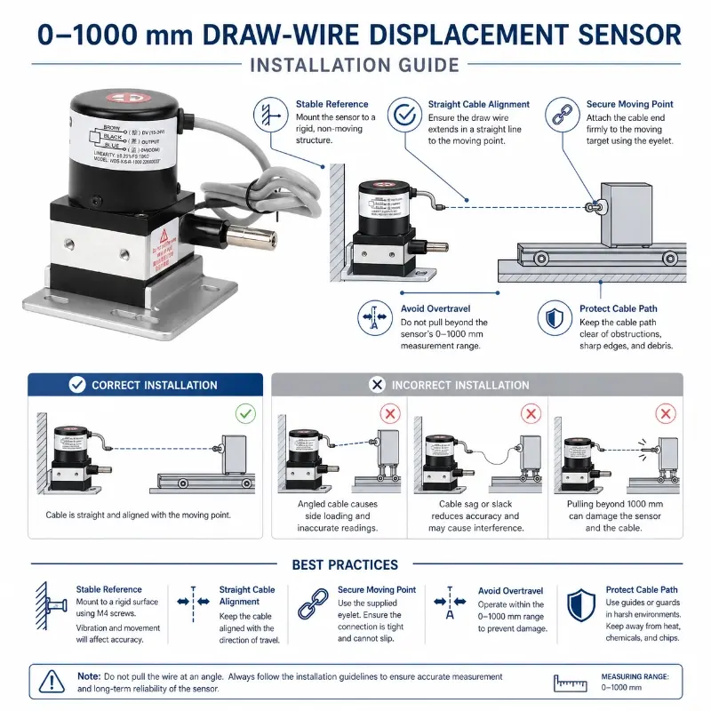
Install the Sensor Body on a Stable Reference
The sensor housing should be fixed to a rigid point that is not expected to move with the monitored target.
If both ends move together, the measured value may not represent the required deformation.
Align the Cable with the Movement Direction
The cable should extend and retract in line with the expected movement.
Excessive lateral angle may cause:
Cable rubbing
Outlet wear
Measurement error
Return problems
Premature cable damage
Keep the Cable Path Clear
Do not allow the cable to contact:
Sharp edges
Concrete corners
Steel mesh
Rocks
Moving equipment
Bolts
Vegetation
Accumulated debris
Do Not Release the Cable Suddenly
When installing or testing, control the cable manually.
Allowing it to retract suddenly may damage the internal mechanism or cable end.
Do Not Exceed the Measuring Range
Use a mechanical stop or appropriate installation design where uncontrolled movement could pull the cable beyond its rated stroke.
Maintain Appropriate Initial Extension
The cable should have enough initial extension to remain under controlled tension, but the initial extension must be included in the available range calculation.
Protect the Sensor from Water and Debris
Even when the enclosure is suitable for outdoor use, installation should reduce direct exposure to:
Standing water
Mud
Falling stones
Concrete slurry
Dust accumulation
Snow and ice
High-pressure water
Chemical splash
Secure the Cable Endpoint
The cable endpoint should be attached to a stable moving point using suitable hardware.
The connection should not rotate, loosen or create sideways loading.
Protect Signal Cables
Use:
Waterproof junction boxes
Cable conduit
Shielded signal cable
Grounding
Surge protection
Drip loops
UV-resistant cable ties
according to the project environment.
Common Installation Errors
1. Selecting a Range Without Safety Margin
A sensor may be damaged if expected movement approaches the full available travel.
2. Installing the Cable at a Large Angle
Side loading increases friction and may reduce cable life.
3. Using an Unstable Reference Point
The output may combine movement from both the sensor body and monitored target.
4. Allowing the Cable to Rub Against Structures
Friction can create measurement errors and mechanical wear.
5. Ignoring Cable Retraction
The return path must remain clear across the complete movement range.
6. Installing Without Mechanical Protection
Construction debris, vehicles, animals or maintenance work may damage exposed cables.
7. Incorrect Signal Scaling
The data logger must use the correct relationship between electrical output and displacement.
Data Interpretation and Alarm Settings
A single displacement reading should not normally be used as the only basis for an engineering decision.
Useful monitoring indicators include:
Total displacement
Incremental displacement
Hourly change
Daily change
Movement rate
Acceleration
Reversal or recovery
Rainfall correlation
Temperature correlation
Multi-sensor consistency
Alarm thresholds should be determined by qualified engineers based on:
Structural design
Geological conditions
Historical movement
Construction stage
Measurement uncertainty
Sensor range
Risk level
Emergency-response plan
A typical platform may apply:
Attention threshold
Warning threshold
Critical threshold
Rate-of-change alarm
Communication-loss alarm
Sensor-range alarm
Maintenance Recommendations
Regularly inspect:
Cable surface
Cable outlet
Retraction condition
Cable endpoint
Mounting bolts
Sensor alignment
Housing sealing
Signal cable
Connector
Junction box
Grounding
Surge protection
Abnormal zero shift
Unexpected output jumps
Clean the cable path and remove materials that could interfere with movement.
Do not apply lubricant unless it is approved for the actual sensor and cable assembly.
How to Choose Between 1000 mm and 2500 mm
Choose the 0–1000 mm model when:
The expected movement is below one metre;
The installation area is compact;
A smaller sensor body is preferred;
The monitored movement is relatively controlled;
High travel beyond one metre is unlikely.
Choose the 0–2500 mm model when:
The expected movement may exceed one metre;
The site requires greater safety margin;
The application involves larger slope or structural movement;
1. What is a draw wire displacement sensor used for?
A
A draw wire displacement sensor is used to measure linear movement, stroke length, and position change in machinery, gates, hydraulic systems, lifting equipment, and automation systems.
Q
2. What measuring range does this sensor support?
A
This model is designed for compact displacement measurement, with a typical range from 0 to 1000mm.
Q
3. Can this sensor be used in outdoor or humid environments?
A
Yes. With IP65 protection, it can be used in many industrial environments where dust and moisture protection are required.
Q
4. Is this sensor suitable for gate opening control?
A
Yes. It can monitor the opening position of gates, doors, and mechanical moving parts by measuring the linear travel distance.
Q
5. Can JW-IoT provide this sensor for OEM equipment integration?
A
Yes. JW-IoT can support OEM style applications where compact displacement sensors are needed for machinery, automation systems, and position feedback solutions.
Q
6. What output signals are available?
A
Depending on configuration, draw wire sensors can support resistance, voltage, current, or digital signal output options for different control systems.
Q
7. Why choose a draw wire sensor instead of a standard linear sensor?
A
A draw wire sensor is easier to install in limited spaces and can measure long or flexible motion paths where rigid linear sensors may not be suitable.
Q
8. Can JW-IoT support application selection for different stroke lengths?
A
Yes. JW-IoT can help users select suitable measuring ranges, output types, and installation methods based on the target machine or monitoring system.
Q
9. Is JW-IoT able to support industrial automation projects using this sensor?
A
Yes. JW-IoT can integrate draw wire displacement sensors into position monitoring, equipment automation, and remote data acquisition solutions.
 +86 13520127780
  info@jingelway.com