+86 13520127780
  info@jingelway.com








Best Practices for Installing Solar PV Weather Stations
Release time: 2026-07-19
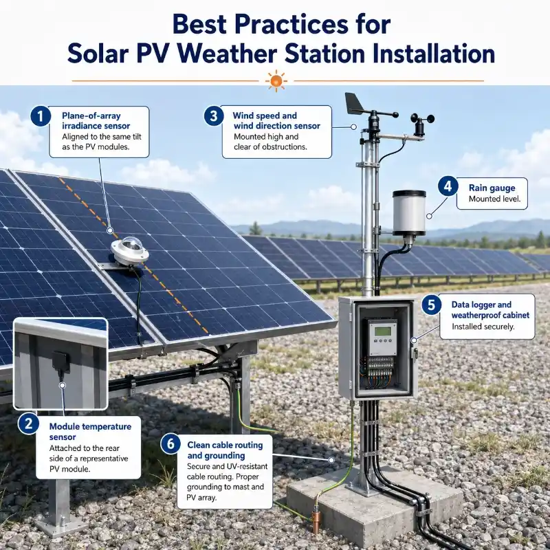
Quick Answer
A solar PV weather station should be installed in a location that accurately represents the operating environment of the PV array.
The most important installation requirements are:
- Align the plane-of-array irradiance sensor with the same tilt and azimuth as the PV modules.
- Keep irradiance sensors free from shading, reflections, dust traps, and nearby obstructions.
- Attach module temperature sensors firmly to the rear surface of representative PV modules.
- Install wind and rainfall sensors where mounting structures and nearby objects will not distort measurements.
- Protect the data logger, power supply, communication equipment, and terminals inside a suitable outdoor cabinet.
- Verify sensor readings, timestamps, communication, and data units before commissioning the station.
Even a high-accuracy sensor can produce unreliable data when it is installed in the wrong location or at the wrong angle.
Why PV Weather Station Installation Affects Data Quality
A PV weather station does more than record local weather. It provides the environmental data needed to explain how a solar power plant is performing.
Typical measurements include:
- Plane-of-array irradiance
- Global horizontal irradiance
- PV module temperature
- Ambient temperature and humidity
- Wind speed and direction
- Rainfall
- Atmospheric pressure
- Rear-side irradiance for bifacial PV projects
- Soiling conditions
These measurements may be used for:
- Performance ratio calculations
- Energy yield analysis
- Fault identification
- Cleaning schedule optimization
- Thermal loss analysis
- Warranty verification
- Operation and maintenance planning
The quality of calculated PV performance indicators depends directly on the accuracy, completeness, consistency, and reliability of the input data. A poorly positioned irradiance sensor or a loose module temperature probe can create misleading performance results, even when the sensor itself is functioning correctly.
For example, an irradiance sensor that is only a few degrees away from the plane of the PV modules may measure a different solar resource from the one actually received by the array. Similarly, a temperature sensor that is not in full contact with the module surface may respond more to ambient air than to module temperature.
Installation should therefore be treated as part of the measurement system—not simply as a mechanical task completed after the equipment arrives.
For projects requiring integrated irradiance, temperature, wind, rainfall, data acquisition, and remote communication, explore the PV Plant Weather Station.
1. Choose a Representative Installation Location
The first step in solar weather station installation is selecting a location that represents the actual conditions experienced by the PV array.
A convenient location is not always a representative location.
The station should not be placed simply because it is close to a control room, access road, inverter station, or available mounting pole. These locations may be affected by shade, reflected heat, dust, vehicle movement, structures, or unusual airflow.
A suitable location should:
- Receive solar exposure similar to the monitored PV array.
- Be free from routine shading throughout the day and year.
- Avoid shadows from module rows, poles, fences, buildings, trees, antennas, and communication equipment.
- Be accessible for inspection, cleaning, and calibration.
- Be protected from construction traffic and accidental impact.
- Allow secure cable routing and grounding.
- Represent the same terrain, elevation, dust exposure, and microclimate as the monitored section of the plant.
For a large utility-scale solar farm, one weather station may not be enough. Different sections of the site can experience different cloud cover, terrain effects, wind conditions, soiling levels, or tracker positions.The number and distribution of monitoring points should be determined by plant size, terrain, array orientation, tracker layout, and local microclimate. For a broader site-planning method, see how to design weather monitoring points for IoT projects.
Larger installations and projects with multiple mounting configurations may require several irradiance sensors or monitoring stations to capture spatial differences across the site.
Avoid installing the station:
- Directly beside a reflective metal cabinet
- Under overhead cables
- Near exhaust outlets or ventilation equipment
- At the lowest point of a flood-prone area
- Immediately beside a dusty access road
- Behind a row of modules that creates morning or afternoon shade
- Where routine maintenance requires technicians to step over sensors or cables
Before finalizing the location, conduct a simple shading assessment and check the solar path for both summer and winter conditions.
2. Best Practices for Irradiance Sensor Installation
Irradiance is one of the most important inputs in PV performance monitoring. A properly selected solar irradiance sensor for PV monitoring helps operators compare available solar energy with actual plant output.
PV systems may use several types of irradiance measurements:
- Plane-of-array irradiance, or POA
- Global horizontal irradiance, or GHI
- Rear-side irradiance for bifacial modules
- Diffuse horizontal irradiance
- Direct normal irradiance for specialized applications
If you need a clearer explanation of sensor principles, measurement types, and their role in plant evaluation, read our guide to solar irradiance sensors for accurate PV performance monitoring.
Plane-of-array irradiance represents the total solar irradiance received on the same plane as the PV modules. Its value depends on array orientation, tilt, solar position, diffuse radiation, reflected radiation, and shading.
Align the POA sensor with the PV modules
For fixed-tilt PV arrays, the POA irradiance sensor should have:
- The same tilt angle as the PV modules
- The same azimuth as the PV modules
- An unobstructed view of the sky
- Exposure to the same shading and soiling environment as the monitored array
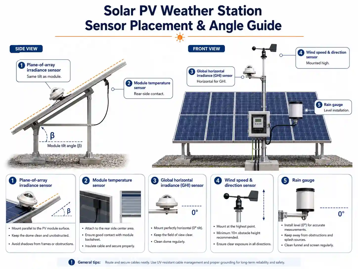
The sensor should be mounted co-planar with the PV array rather than merely attached to a nearby horizontal surface. POA irradiance is specifically measured with the pyranometer or reference cell positioned in the same plane as the PV modules.
Use a rigid, adjustable mounting bracket and verify the angle with a calibrated digital inclinometer. Do not rely only on visual alignment.
For projects using different module orientations—for example, east-facing and west-facing rooftop arrays—install a separate POA sensor for each major orientation.
Keep the sensor free from shade
Check for both permanent and temporary shading from:
- PV module frames
- Torque tubes
- Tracker drives
- Mounting poles
- Cable trays
- Lightning protection equipment
- Antennas
- Nearby sensors
- Vegetation
- Technician access platforms
A sensor may appear unshaded at midday but still be shaded in the early morning or late afternoon. Seasonal changes in the sun’s path should also be considered.
Avoid unwanted reflections
Do not install the sensor where nearby metal surfaces, glass, white walls, roofs, or other reflective objects can add abnormal reflected radiation.
The objective is to measure the solar resource received by the PV array, not the localized reflection created by surrounding equipment.
Ensure correct leveling for horizontal measurements
A GHI pyranometer should be installed horizontally and carefully leveled using the built-in bubble level or an appropriate leveling base.Projects requiring higher-grade solar radiation measurements can use a Class A pyranometer with RS485 output for integration with data loggers, SCADA systems, and PV weather stations.
Accurate leveling matters because pyranometers respond to the angle at which radiation reaches the sensing surface. Appropriate mounting bases commonly use bubble levels and adjustable screws to maintain the correct horizontal position.
After tightening the mounting bolts, check the level again. Tightening one side of the bracket can change the final angle.
Install sensors on trackers correctly
For single-axis tracking systems, the POA sensor should follow the same movement as the monitored tracker row.
Mount it to a structurally stable part of the tracker so that:
- The sensor plane remains parallel to the module plane.
- The bracket does not twist during movement.
- The sensor does not shade the PV modules.
- Cabling allows the full tracker range without stretching or abrasion.
- The tracker structure does not block the sensor’s field of view.
For large tracker plants, consider how tracker mismatch, backtracking, terrain variation, and row-to-row differences may affect representativeness.
Plan for cleaning and inspection
Dust, bird droppings, frost, snow, water spots, and insect contamination can reduce irradiance readings.
The sensor should be easy to reach without requiring technicians to climb onto modules or disconnect cables. Establish an inspection and cleaning schedule appropriate for the local climate.
Use only manufacturer-approved cleaning materials. Abrasive tools or aggressive chemicals can damage a sensor dome or diffuser.
For accurate plane-of-array monitoring, see the [Solar Irradiance Sensor] designed for PV performance analysis and environmental monitoring.
3. How to Install PV Module Temperature Sensors
PV module temperature has a direct effect on electrical performance. A PV module temperature sensor is normally attached to the rear surface of a representative module to measure its real operating temperature.
The purpose of a module temperature sensor is to measure the operating temperature of a representative PV module—not the temperature of the surrounding air.
Select a representative module
Choose a module that reflects normal operating conditions within the monitored array.
Avoid modules that are:
- At an unusually exposed row edge
- Permanently shaded
- Directly above a hot roof feature
- Close to an inverter or ventilation outlet
- Damaged or heavily soiled
- Located in an area with abnormal airflow
- Easy to access but unrepresentative of the array
For a large plant, use multiple module temperature sensors across representative blocks, orientations, or tracker zones.
Attach the sensor to the rear surface
The sensor should be installed on the backsheet or rear surface of the PV module according to the sensor manufacturer’s instructions.
General best practices include:
- Clean and dry the installation area.
- Position the sensor away from the module frame and junction box.
- Ensure full thermal contact between the sensor and module surface.
- Secure it with an appropriate thermally conductive adhesive, tape, or mounting pad.
- Protect the sensor cable from movement and mechanical stress.
- Avoid creating air gaps between the sensing element and the module.
A loose sensor can measure a mixture of module and ambient air temperature, producing unstable or consistently low readings.
Choose a suitable position on the module
A common approach is to position the sensor near the central region of the rear surface, away from the junction box, frame, and edges.
However, the final location should follow the module layout, sensor type, project specification, and applicable monitoring standard.
Do not attach the sensor directly over:
- Junction boxes
- Bypass diode areas
- Frame members
- Damaged backsheet sections
- Cable connectors
- Adhesive residues from previous sensors
Provide strain relief
Module movement, wind vibration, thermal expansion, tracker rotation, and maintenance work can pull on the cable.
Secure the cable close to the sensor to prevent the sensing element from being lifted away from the module. Use UV-resistant cable ties, clips, or conduit suitable for outdoor solar installations.
Do not pull cables tightly. Leave enough allowance for thermal movement and tracker operation.
Verify the reading after installation
Compare the module temperature reading with:
- Nearby module temperature sensors
- Ambient temperature
- Irradiance conditions
- Expected daytime temperature behavior
On a sunny day, module temperature will normally rise above ambient temperature. A sensor that remains close to ambient temperature under strong irradiance may have poor thermal contact or may not be attached to the intended surface.
Learn more about continuous module surface monitoring with the PV Module Temperature Sensor.
4. Wind Sensor Placement
Wind speed and wind direction data can support:
- PV module temperature analysis
- Structural load assessment
- Tracker control
- Extreme weather alarms
- Cooling and heat-loss models
- Site condition analysis
Wind sensors are especially sensitive to nearby obstructions.
Keep the sensor away from turbulence
Buildings, module rows, cabinets, fences, trees, and poles can create turbulent airflow and distorted readings.
Install the wind sensor:
- Above or away from nearby obstacles
- On a rigid vertical mast
- Where airflow is as unobstructed as practical
- Away from heat exhausts
- Outside the wake created by large structures
The ideal mounting height depends on the measurement objective and project specification. A sensor used for plant microclimate analysis may be installed differently from one intended to represent a standardized meteorological measurement height.
Consistency is important. Record the final installation height and surrounding conditions in the commissioning documentation.
Orient the wind direction sensor correctly
Use a compass corrected for local magnetic declination, verified site coordinates, or another approved survey method to establish true north.
Do not assume that a mounting rail, building edge, or PV row is precisely aligned with north.
After orientation:
- Confirm the wind vane moves freely.
- Check that the north reference is correctly configured in the data logger.
- Verify that cable routing does not restrict rotation.
- Compare the reading with observed wind direction during commissioning.
5. Rain Gauge Placement
Rainfall data may help operators understand:
- Natural module cleaning
- Soiling changes
- Storm events
- Site drainage conditions
- Maintenance access
- Correlations between rain and power recovery
The rain gauge should be level, stable, and clear of splash or obstruction.
Installation recommendations
- Install the gauge on a stable, vibration-free support.
- Make sure the collector opening is horizontal.
- Keep it away from roofs, module edges, trees, poles, and tall structures.
- Avoid locations where water can splash into the collector.
- Prevent cable routes from interfering with the tipping mechanism.
- Use insect protection if recommended by the manufacturer.
- Check that the funnel and drainage path are clear.
A tipping-bucket rain gauge that is not level can systematically undercount or overcount rainfall.
After installation, perform a controlled test using a known volume of water according to the manufacturer’s procedure. Confirm that each tip is recorded correctly by the data logger.
6. Ambient Temperature and Humidity Sensor Installation
Ambient temperature and humidity sensors must measure the surrounding air rather than direct solar heating.
Install these sensors inside a suitable radiation shield.
The shield should:
- Protect the sensor from direct and reflected solar radiation
- Allow adequate natural or forced ventilation
- Reduce exposure to rain
- Be installed away from hot cabinets and module backsheets
- Be positioned where air can circulate freely
Do not mount an unshielded temperature sensor directly onto a metal pole. The pole can heat up in sunlight and create a false high-temperature reading.
Avoid installation immediately above:
- Dark roofing materials
- Concrete surfaces
- Inverter exhausts
- Transformer areas
- Reflective metal cabinets
Document the installation height so that future replacement sensors can be installed consistently.
7. Bifacial PV Weather Station Installation
Bifacial PV projects require additional attention because energy is generated from both front-side and rear-side irradiance.
Rear-side irradiance depends on:
- Ground albedo
- Row spacing
- Module height
- Tracker position
- Surface conditions
- Shading from structural components
- Terrain geometry
- Snow or vegetation cover
A single rear-side sensor may not adequately represent a large or non-uniform bifacial array.
Rear-side sensor considerations
- Install the sensor behind the module plane according to the monitoring design.
- Avoid shade from torque tubes, rails, junction boxes, and cables.
- Maintain the specified distance from the module.
- Use multiple measurement positions when rear irradiance varies significantly.
- Record the exact sensor geometry for future data interpretation.
- Consider separate albedo monitoring where required.
Bifacial irradiance monitoring is more sensitive to local geometry than conventional front-side POA monitoring. Project developers should therefore define sensor positions before construction rather than improvising them during commissioning.
Floating PV projects introduce additional challenges such as humidity, corrosion, water-level variation, access limitations, and platform movement. These projects may require a dedicated floating solar monitoring station solution.
8. Data Logger and Outdoor Cabinet Installation
The data logger is the central point where sensor signals are collected, processed, stored, and transmitted.
A reliable installation must protect both data quality and equipment availability.
Select a suitable cabinet
The cabinet should provide protection appropriate for local conditions, including:
- Rain and water ingress
- Dust
- Humidity and condensation
- Solar heating
- Corrosive environments
- Insects
- Unauthorized access
- Cable strain
- Electrical surges
Install the cabinet above expected flood or standing-water levels.
In hot climates, avoid placing it where it receives unnecessary direct afternoon sun. Use a sun shield, ventilation system, insulation, or climate control where required.
Separate signal and power wiring
Route low-level sensor signals separately from:
- AC power cables
- Inverter cables
- Motor cables
- Tracker power cables
- High-current DC cables
- Radio transmitters
This reduces the risk of electrical interference.
Use shielded cable where specified, and follow the manufacturer’s grounding instructions. Incorrect grounding at multiple points can introduce ground loops.
Label every cable
Each cable should be labeled at both ends with:
- Sensor name
- Channel number
- Station ID
- Cable destination
Clear labels reduce commissioning time and make future troubleshooting much easier.
Also maintain a wiring diagram inside the cabinet or in the digital project documentation.
Provide surge and lightning protection
PV plants are exposed sites where long cable runs can collect surge energy.
The installation plan should consider:
- Signal-line surge protection
- Power-line surge protection
- Mast grounding
- Cabinet grounding
- Cable shielding
- Lightning protection coordination
- Communication port protection
Grounding and surge protection should follow local electrical codes, project requirements, and the equipment manufacturer’s recommendations.
Confirm the power supply
Before connecting sensors, verify:
- Input voltage
- Power polarity
- Peak current requirements
- Solar power and battery sizing, where applicable
- Backup operating time
- Charging controller settings
- Fuse ratings
- Low-voltage protection
A weather station may work normally during sunny commissioning conditions but fail at night or during extended cloudy weather if its battery and solar power system are undersized.
Where a project requires an integrated station rather than individually assembled sensors, the solar PV weather station with irradiance monitoring combines key meteorological and module-related parameters in one monitoring system.
9. Communication and Data Configuration
PV weather stations may communicate through:
- RS485 Modbus
- Ethernet
- 4G LTE
- LoRaWAN
- Wi-Fi
- Fiber networks
- MQTT
- Private cloud platforms
- SCADA systems
For data mapping, protocol selection, platform connectivity, and system architecture, see our guide to integrating PV weather stations with SCADA and cloud platforms.
Physical installation is only complete when data arrives correctly at the intended platform.
Configure each sensor carefully
Check:
- Device address
- Communication protocol
- Baud rate
- Parity and stop bits
- Register mapping
- Engineering units
- Decimal position
- Sampling interval
- Storage interval
- Upload interval
- Alarm threshold
- Time zone
- Time synchronization
A common integration error is receiving technically valid data in the wrong unit—for example, interpreting temperature as a raw integer or rainfall totals as rainfall intensity.
Use a consistent timestamp
All station data should use a clearly defined time reference.
Confirm:
- Local time or UTC
- Daylight saving time behavior
- Network time synchronization
- Data logger clock accuracy
- Timestamp location in the data packet
- Handling of communication outages
Consistent timestamps are essential when weather data is compared with inverter, meter, tracker, and SCADA data.
Maintain local data storage
Where possible, configure the logger to store data locally during communication interruptions.
Once the connection is restored, the system should be able to upload historical records without creating duplicate or disordered data.
10. Recommended Sampling and Logging Strategy
Fast sampling captures short-term variation, while the logging interval determines how frequently processed values are stored.
The best configuration depends on:
- Sensor response time
- Plant monitoring requirements
- Performance calculation method
- SCADA capacity
- Communication bandwidth
- Storage capacity
- Contractual or regulatory requirements
For example, an irradiance sensor may be sampled more frequently than the final averaging interval. The logger can then calculate average, minimum, maximum, standard deviation, or totalized values.
Do not use a long upload interval as a substitute for proper local sampling. A station that uploads once every 15 minutes can still sample sensors more frequently and transmit calculated results.
Before commissioning, verify that the averaging method used by the weather station is compatible with the method used for plant power and energy data.
11. Common PV Weather Station Installation Mistakes
Many data-quality problems can be traced back to a small number of installation errors.
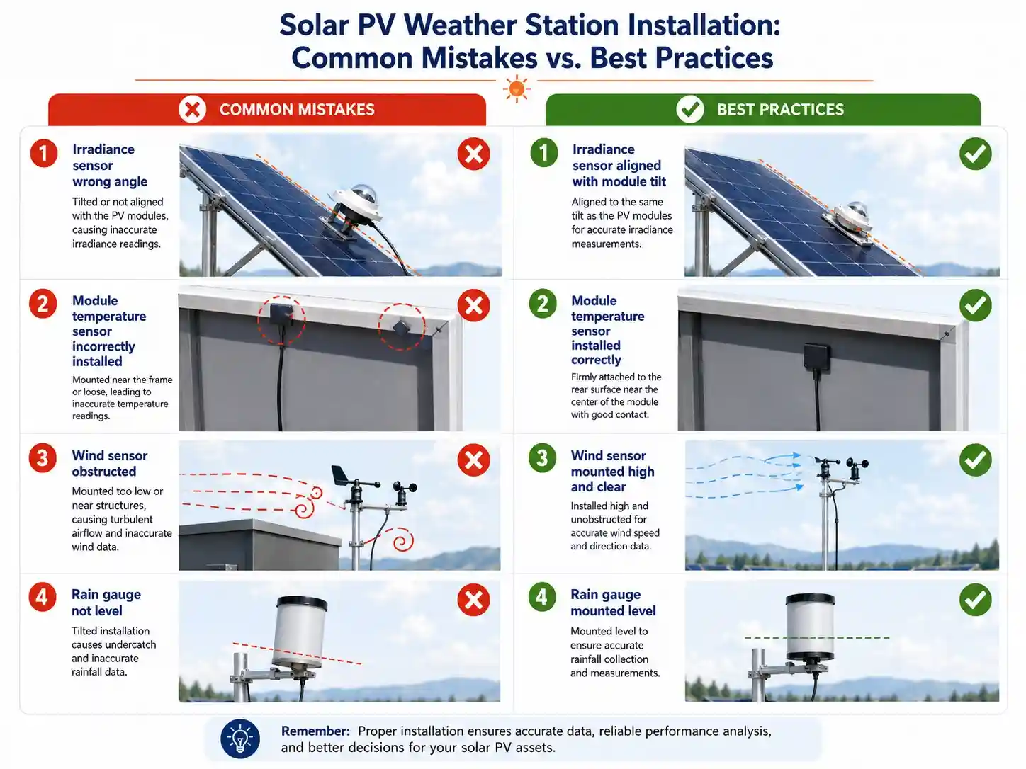
Mistake 1: Installing the POA sensor horizontally
A horizontal irradiance sensor does not represent the irradiance received by a tilted PV array.
Better approach: Align the POA sensor with the same tilt and azimuth as the modules.For applications where the monitoring response should closely reflect crystalline silicon PV modules, a silicon irradiance sensor for PV performance monitoring may also be considered.
Mistake 2: Mounting the sensor according to the support frame rather than the module plane
Mounting structures are not always perfectly parallel to the modules.
Better approach: Measure the actual module angle and align the sensor independently.
Mistake 3: Ignoring seasonal shading
A sensor that is clear in summer may be shaded in winter.
Better approach: Review the full annual solar path before finalizing the mounting position.
Mistake 4: Installing a module temperature sensor near the frame
Module edges may have different thermal behavior from the central module area.
Better approach: Select a representative rear-surface position away from the frame and junction box.
Mistake 5: Leaving an air gap beneath the temperature sensor
Poor contact causes slow or inaccurate temperature response.
Better approach: Ensure full contact and use the specified attachment material.
Mistake 6: Installing wind sensors beside a cabinet or module row
Nearby structures disturb airflow.
Better approach: Use a clear mounting position with minimal turbulence.
Mistake 7: Failing to level the rain gauge
A tilted rain gauge can produce systematic measurement errors.
Better approach: Level the gauge during installation and recheck it after tightening.
Mistake 8: Routing sensor cables with high-power cables
Electrical noise can affect sensor or communication signals.
Better approach: Separate signal and power wiring and follow grounding requirements.
Mistake 9: Forgetting strain relief
Cable movement can loosen terminals or detach surface sensors.
Better approach: Secure cables near each sensor while allowing for thermal and mechanical movement.
Mistake 10: Commissioning the hardware without checking the data
A powered sensor is not necessarily producing correct data.
Better approach: Validate readings, units, timestamps, communication status, and expected environmental relationships.
12. Commissioning Checklist
Complete the following checks before accepting the PV weather station.
Mechanical checks
- All masts, brackets, and cabinets are securely fixed.
- Sensor angles match the approved drawings.
- The POA sensor matches the module tilt and azimuth.
- Horizontal pyranometers and rain gauges are level.
- Module temperature sensors have full surface contact.
- Tracker-mounted cables move freely.
- All connectors are weatherproof.
- Cables have suitable strain relief.
- No sensor is shaded by the mounting structure.
- The station is accessible for maintenance.
Electrical checks
- Supply voltage and polarity are correct.
- Grounding connections are complete.
- Surge protection is installed.
- Cable shields are terminated correctly.
- Signal and power cables are separated.
- Fuses and breakers are correctly rated.
- Battery voltage and charging status are normal.
- Cabinet terminals are labeled.
Data checks
- Every sensor is reporting.
- Values use the correct engineering units.
- Device addresses match the configuration file.
- Timestamps are correct.
- Sampling and logging intervals are correct.
- Data reaches the cloud or SCADA platform.
- Local storage works during a communication interruption.
- Alarm thresholds are configured.
- Historical records can be retrieved.
- Sensor readings are physically reasonable.
13. Validate the Data Before Leaving the Site
A final data validation can identify installation problems that visual inspection misses.
Compare related measurements
Review relationships between:
- POA irradiance and PV power
- GHI and POA irradiance
- Module temperature and ambient temperature
- Module temperature and irradiance
- Wind speed and module cooling
- Rainfall and soiling recovery
- Front-side and rear-side irradiance
- Multiple sensors installed at the same site
For example:
- Module temperature should generally rise as irradiance increases.
- PV power should broadly follow irradiance during normal operation.
- Two similarly positioned irradiance sensors should show similar patterns.
- A POA sensor should not remain at zero while the plant is generating normally.
- Rainfall totals should not increase on a dry day.
Check data during different conditions
A single midday test is not enough.
Where possible, review data during:
- Sunrise
- Midday
- Sunset
- Tracker movement
- Cloud transitions
- High-wind periods
- Rainfall events
- Nighttime operation
- Communication outages
This helps reveal shading, tracker cable problems, timestamp errors, unstable power supplies, and abnormal nighttime offsets.
14. Maintenance After Installation
Accurate PV monitoring requires continued maintenance.
Create a maintenance plan covering:
- Sensor cleaning
- Visual inspection
- Level and angle verification
- Cable and connector inspection
- Cabinet sealing
- Grounding inspection
- Battery testing
- Data-gap review
- Sensor comparison
- Calibration
- Vegetation control
- Firmware and configuration backup
Compare measured irradiance with expected clear-sky behavior over time. Persistent deviation can indicate sensor drift, contamination, shading, alignment changes, or calibration problems. Comparing sensor data with modeled irradiance during clear periods is one method used to identify drift and abnormal measurements.
Calibration frequency should follow the sensor manufacturer’s recommendations, the project monitoring class, and contractual requirements. Some high-quality monitoring practices call for periodic recalibration of irradiance sensors, with the interval depending on sensor class and application.
Keep records of every maintenance action, including:
- Date
- Technician
- Sensor ID
- Work completed
- Calibration information
- Before-and-after readings
- Photos
- Configuration changes
These records are valuable when investigating long-term performance changes.
FAQ
What is the most important rule for PV weather station installation?
The most important rule is to install every sensor where it represents the conditions experienced by the PV array. For plane-of-array irradiance, this means matching the tilt and orientation of the PV modules and avoiding shade or abnormal reflections.
Where should a solar irradiance sensor be installed?
A POA irradiance sensor should be installed in an unshaded, representative location with the same tilt and azimuth as the monitored PV modules. A GHI sensor should normally be installed horizontally and carefully leveled.
Does every PV plant need a weather station?
A weather station is particularly valuable when the plant operator needs to calculate performance ratio, identify environmental causes of underperformance, evaluate thermal losses, manage cleaning, verify warranties, or compare actual output with available solar resource.
The number and type of stations depend on plant size, terrain, module orientation, tracker design, climate, and monitoring objectives.
How many irradiance sensors are needed for a solar farm?
There is no single number suitable for every project. A small, uniform site may use one representative measurement location, while a large site with different terrains, orientations, tracker blocks, or microclimates may require several sensors or weather stations.For rooftop arrays and geographically distributed generation sites, a compact PV weather monitoring station for distributed solar plants can provide localized data for each representative site.
Where should a PV module temperature sensor be placed?
It is generally attached firmly to the rear surface of a representative PV module, away from the frame, module edge, and junction box. The exact position and attachment method should follow the sensor manufacturer’s instructions and project monitoring requirements.
Why is my module temperature reading close to ambient temperature?
Possible reasons include poor contact with the module, an air gap beneath the sensor, installation on the wrong surface, shading, a loose cable, incorrect channel configuration, or a failed sensor.
Should a weather station be installed near the control room?
Only when the control-room area represents the same environmental conditions as the PV array. Convenience should not take priority over representative measurement.
How often should irradiance sensors be cleaned?
Cleaning frequency depends on local dust, rainfall, snow, bird activity, agriculture, construction, and industrial pollution. Sensors should be inspected frequently enough to prevent contamination from creating a meaningful measurement bias.
Can one POA sensor monitor east- and west-facing arrays?
One sensor cannot accurately represent two significantly different array orientations. Install a separate POA sensor for each major tilt or azimuth group when their irradiance conditions differ.
What should be tested during commissioning?
Test sensor readings, engineering units, timestamps, data logger channels, communication, local storage, power backup, alarms, cable movement, grounding, and the relationship between weather data and PV output.
Final Takeaway
Reliable PV performance monitoring begins with correct installation.
A well-designed weather station can still deliver poor data when:
- The irradiance sensor is installed at the wrong angle.
- The module temperature sensor has poor thermal contact.
- The wind sensor is affected by turbulence.
- The rain gauge is not level.
- The logger uses incorrect units or timestamps.
- Sensors are difficult to inspect and maintain.
The best installation is not necessarily the most convenient one. It is the installation that produces representative, traceable, and maintainable data throughout the operating life of the PV plant.
JW-IoT provides configurable PV environmental monitoring solutions that can integrate irradiance, PV module temperature, ambient weather, wind, rainfall, soiling, data logging, RS485 Modbus, 4G LTE, LoRaWAN, MQTT, API, and cloud-platform communication.