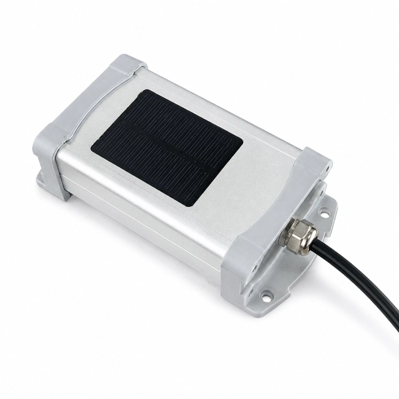
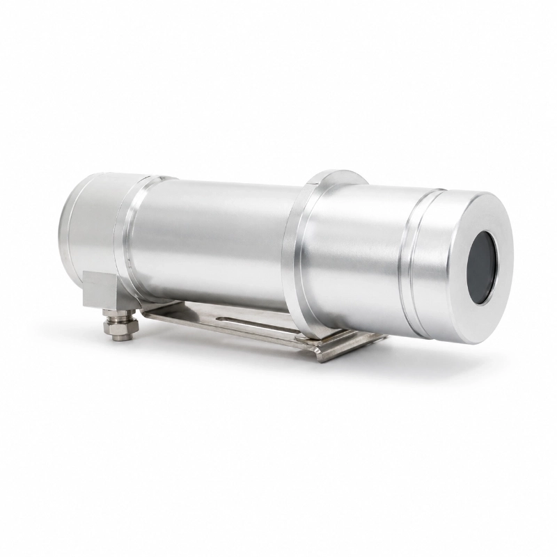
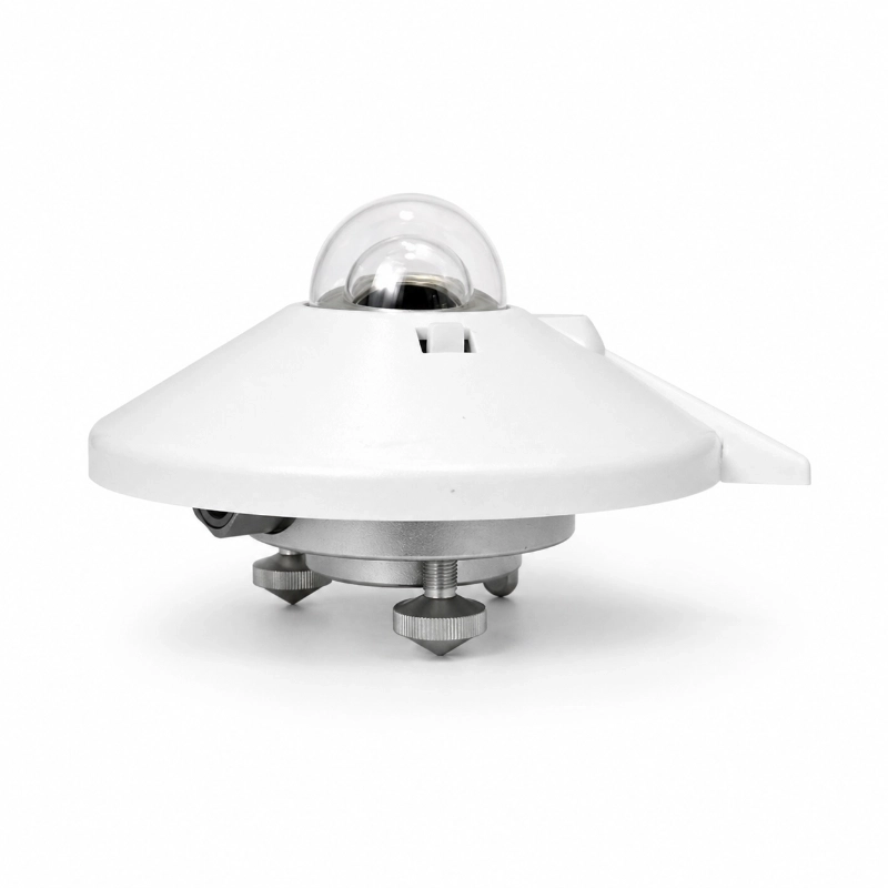
RS485 Modbus PV Reference Cell for Plane-of-Array Irradiance Measurement
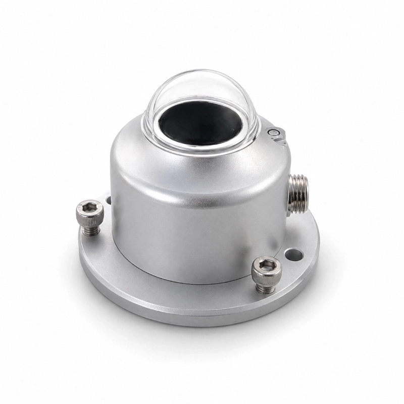
The JW-TBQ-GJ(LC13) Silicon Irradiance Sensor is a photovoltaic reference-cell sensor developed for measuring solar irradiance in PV power plants, rooftop solar systems, module testing projects and solar weather stations.
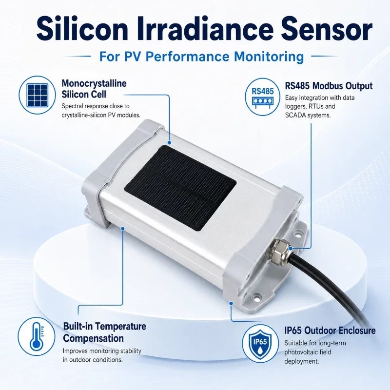
It uses a monocrystalline silicon sensing cell with a spectral response similar to that of conventional crystalline-silicon PV modules. This allows the sensor to provide irradiance data that closely reflects the solar energy available to the monitored PV array.
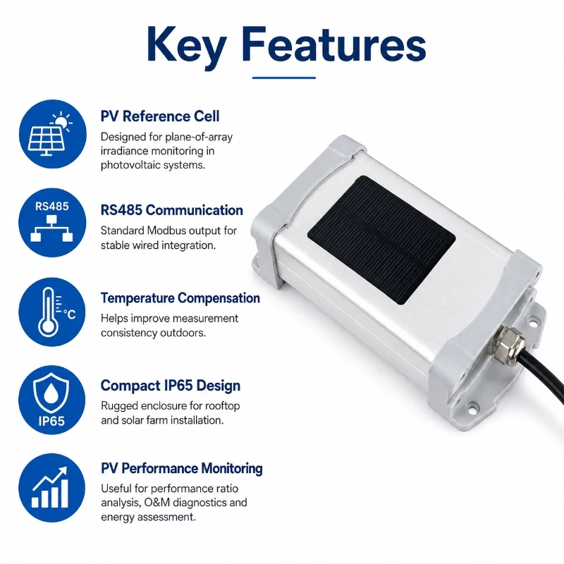
With RS485 output, standard Modbus communication, built-in temperature compensation and an IP65 outdoor enclosure, the sensor can be connected to data loggers, RTUs, PLCs, SCADA systems and PV monitoring platforms.
It can operate as an independent irradiance sensor or be integrated into a complete renewable energy monitoring solution with weather sensors, module temperature sensors, communication equipment and cloud-based data management.
Product Overview
The JW-TBQ-GJ(LC13) is also commonly described as a:
PV reference cell
Silicon reference cell
Photovoltaic irradiance sensor
POA irradiance sensor
Reference-cell irradiance sensor
Unlike a general-purpose light sensor, it is specifically designed to monitor the solar irradiance received by photovoltaic modules.
Because the sensing element is based on crystalline-silicon technology, its response to sunlight is closer to that of a crystalline-silicon PV module than the response of many broad-spectrum radiation instruments. This makes it suitable for performance comparison, operational analysis and plane-of-array monitoring.
The sensor converts the response of the silicon cell into a digital irradiance reading that can be transmitted through RS485 Modbus to a local controller or remote monitoring platform.
What Does the Sensor Measure?
The sensor measures solar irradiance incident on its sensing surface.
When installed at the same tilt angle and orientation as the PV modules, it can provide plane-of-array irradiance, commonly abbreviated as POA irradiance.
POA irradiance represents the solar energy reaching the tilted surface of the PV array. It is especially useful for comparing:
Available solar irradiance
Expected PV output
Actual inverter output
Module temperature
System efficiency
Performance ratio
Irradiance loss caused by clouds or shading
Differences between PV strings or array sections
The sensor does not directly measure PV power output. Instead, it provides an environmental reference that can be compared with electrical production data.
Why Use a Silicon Reference Cell in a PV Plant?
A PV plant cannot evaluate performance accurately using power output alone.
A reduction in generation may be caused by:
Lower solar irradiance
Passing clouds
High module temperature
Dust or soiling
Partial shading
Module degradation
Inverter limitation
String failure
Cable losses
Grid curtailment
By measuring irradiance close to the PV array, operators can separate changes caused by available sunlight from changes caused by equipment or operational conditions.
For example, lower output during low irradiance may be normal. Lower output under strong irradiance may indicate a system performance problem that requires investigation.
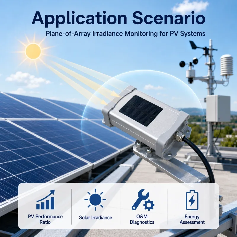
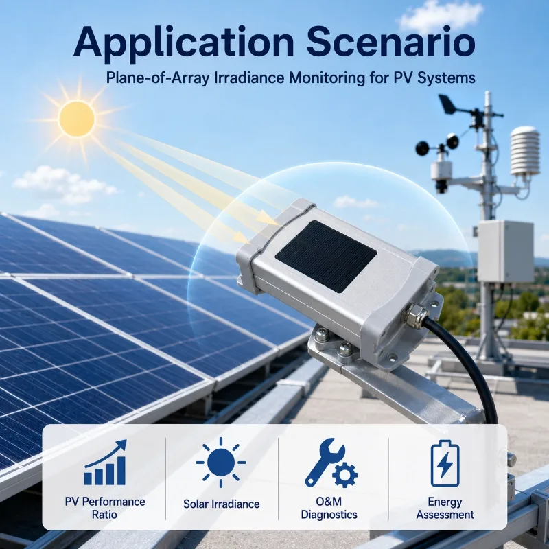
Plane-of-Array Irradiance Monitoring
The sensor is normally installed at the same inclination and azimuth as the monitored PV modules.
This installation method allows the sensing surface to receive sunlight under conditions similar to those experienced by the array.
Plane-of-array data can support:
PV performance ratio analysis
Yield assessment
Inverter performance evaluation
String comparison
Soiling loss analysis
Module degradation studies
Fault detection
O&M reporting
Solar forecasting
Digital twin and analytics platforms
For large solar plants with different array orientations, multiple sensors may be required.
Separate monitoring points may be considered for:
East-facing and west-facing arrays
Different tracker blocks
Fixed-tilt and tracking sections
Different module technologies
Separate inverter zones
Areas with different shading conditions
Geographically distributed plant sections
How the Silicon Irradiance Sensor Works
1. Solar Energy Reaches the Sensing Cell
Sunlight reaches the monocrystalline silicon sensing surface.
2. The Cell Produces an Electrical Response
The silicon cell generates an electrical signal related to the irradiance received by the sensing surface.
3. Temperature Compensation Is Applied
The response of silicon cells changes with temperature.
The built-in temperature compensation function helps reduce measurement deviation caused by changing outdoor temperatures and improves long-term monitoring consistency.
4. The Signal Is Converted into Digital Data
The sensor electronics process the signal and convert it into an irradiance value.
5. Data Is Transmitted Through RS485 Modbus
The measured value is sent to a data logger, RTU, PLC, industrial computer or monitoring platform through the RS485 interface.
RS485 Modbus Communication
The JW-TBQ-GJ(LC13) uses RS485 communication and supports the standard Modbus protocol.
RS485 is suitable for industrial and outdoor monitoring because it supports:
Stable wired communication
Multi-device networks
Long-distance field cabling
Integration with industrial controllers
Standard register-based data reading
Centralized sensor acquisition
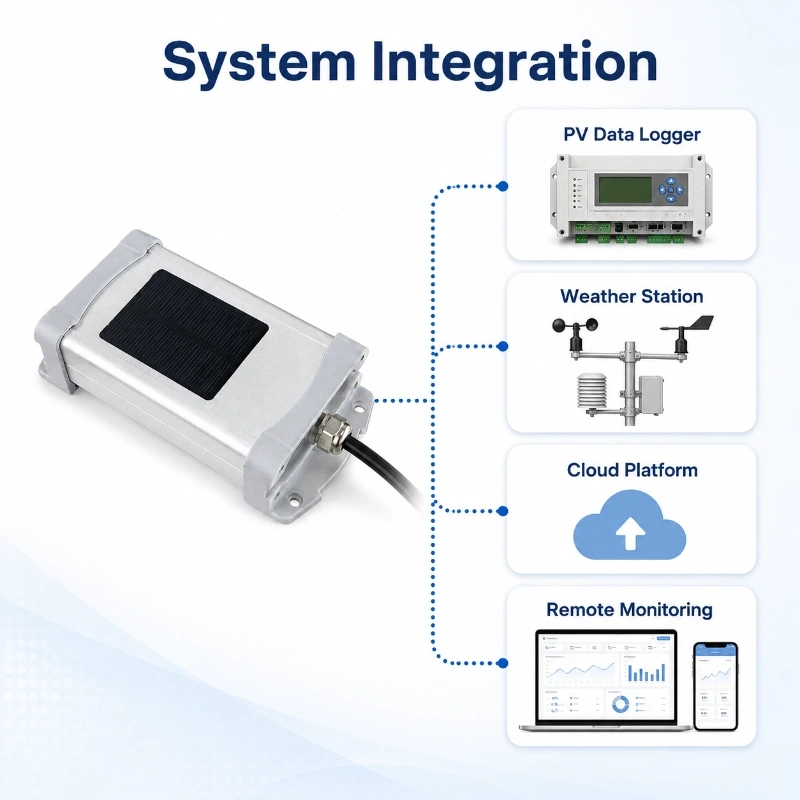
The sensor can be connected to:
PV data loggers
Remote terminal units
PLC systems
SCADA systems
Weather station controllers
Industrial gateways
Edge computing devices
Local monitoring servers
Cloud monitoring platforms
Before system integration, confirm the communication address, baud rate, parity setting, register map and data format in the latest communication protocol document.
Typical Technical Specifications
Item
Specification
Product type
Silicon irradiance sensor
Model
JW-TBQ-GJ(LC13)
Alternative name
PV reference cell
Sensing element
Monocrystalline silicon solar cell
Output interface
RS485
Communication protocol
Standard Modbus
Power supply
12V DC
Temperature compensation
Built in
Protection rating
IP65
Nonlinearity
0.10%
Stability
0.50%
Measurement error
5%
Installation
PV module surface or project-specified mounting
Main application
PV irradiance and performance monitoring
Technical specifications should be confirmed using the latest datasheet before procurement.
For engineering projects, please also confirm:
Irradiance measurement range
Resolution
Response time
Operating temperature range
Storage temperature range
Cable length
Connector type
Modbus register map
Sensor dimensions
Mounting-hole dimensions
Calibration method
Calibration documentation
Surge and lightning protection requirements
Silicon Irradiance Sensor vs Pyranometer
A silicon irradiance sensor and a pyranometer both measure solar irradiance, but they use different sensing technologies and serve different project needs.
Comparison Item
Silicon Irradiance Sensor
Thermopile Pyranometer
Sensing principle
Silicon photovoltaic cell
Thermopile
Spectral response
Similar to silicon PV modules
Broader solar spectrum
Main application
PV performance monitoring
Meteorology and reference-grade radiation monitoring
Response speed
Generally fast
Depends on pyranometer class and design
Cost
Usually more economical
Usually higher
Multi-point deployment
Practical
May increase project cost
PV module matching
Strong for crystalline-silicon arrays
Measures broader-spectrum irradiance
Typical installation
Same tilt as PV modules
Horizontal or plane-of-array
Best suited for
Operational PV monitoring
Meteorological and high-accuracy reference measurement
A silicon sensor is often preferred when the project needs an economical, fast-response irradiance reference closely related to crystalline-silicon PV module behavior.
A thermopile pyranometer may be more suitable when the project requires:
The correct sensor should be selected according to the required accuracy, spectral response, project standard, budget and monitoring purpose.
Silicon Reference Cell vs PV Module Power Data
A silicon reference cell measures incoming solar irradiance.
PV electrical monitoring measures:
DC voltage
DC current
DC power
AC output
Inverter efficiency
Energy yield
These measurements should not replace one another.
The irradiance sensor shows how much solar energy was available. The electrical monitoring system shows how much energy the PV system produced.
Comparing the two datasets helps operators evaluate whether the plant is converting available solar energy into electricity efficiently.
Performance Ratio Monitoring
Performance Ratio, or PR, is commonly used to evaluate normalized PV plant performance.
A simplified project-level comparison uses:
Measured irradiance
Installed PV capacity
Actual energy output
Module temperature
Monitoring period
System losses
The silicon irradiance sensor provides the solar irradiance input required by many PR monitoring systems.
For reliable analysis, irradiance data should be synchronized with:
Inverter data
Meter data
Module temperature
Ambient temperature
Wind conditions
Alarm records
Plant availability
Curtailment periods
Incorrect sensor installation or poor maintenance can directly distort PR results.
Installation Guidelines
Install at the Same Tilt as the PV Array
For plane-of-array measurement, the sensor should match the tilt angle and azimuth of the PV modules being monitored.
Even a small angular difference can create measurement differences, especially when the sun is low.
Avoid Shading
Do not install the sensor where it may be shaded by:
Module frames
Mounting structures
Cables
Junction boxes
Railings
Nearby sensors
Vegetation
Buildings
Tracker components
The sensing surface should receive the same unobstructed sunlight as the monitored modules.
Select a Representative Location
The installation point should represent the operating conditions of the target PV array.
Avoid unusual locations affected by:
Local reflections
Permanent shading
Excessive dust accumulation
Water runoff
Heat exhaust
Snow drifting
Uneven cleaning
Large plants may require several measurement points.
Keep the Sensing Surface Clean
Dust, sand, pollen, bird droppings, salt spray and water stains can reduce the measured irradiance.
The sensor should be inspected and cleaned as part of the PV plant’s regular maintenance schedule.
For soiling studies, make sure the cleaning method is consistent with the monitoring objective.
Protect the Cable
Route the RS485 cable through suitable conduit or cable trays.
Avoid:
Sharp bends
Loose connections
Long unsupported cable sections
Direct contact with hot module backsheets
Water accumulation at connectors
Parallel installation beside high-power cables without suitable separation
Use surge and lightning protection where required by the project design.
Record Installation Information
Document:
Sensor serial number
Installation date
GPS location
Array section
Tilt angle
Azimuth
Cable length
Modbus address
Data logger channel
Calibration information
Maintenance history
This information is important for troubleshooting and long-term data traceability.
Front-Side and Rear-Side Installation
The current product configuration supports installation on the PV panel surface or rear side.
The selected method should match the monitoring objective and mounting accessory.
Front or Plane-of-Array Position
This position is generally used when the sensing cell must directly receive the same sunlight as the PV module surface.
The sensor should not create shading on the active module area.
Rear-Side Mounting Structure
Rear-side mounting may refer to fixing the sensor bracket to the back or frame of the module while keeping the sensing surface oriented toward the sky.
The sensing surface itself should remain unobstructed and aligned with the module plane.
Do not install the active sensing surface facing downward unless the application specifically requires reflected or rear-side irradiance measurement and the product configuration supports it.
Application Scenarios
Utility-Scale PV Power Plants
The sensor can be installed in fixed-tilt or tracking solar plants to support:
Irradiance monitoring
Performance ratio analysis
Inverter-zone comparison
O&M diagnostics
Yield assessment
Fault investigation
Rooftop Solar Systems
For commercial and industrial rooftop PV, the sensor can provide a local irradiance reference for comparing expected and actual system output.
PV Weather Stations
The sensor can be combined with:
Ambient temperature and humidity sensors
PV module temperature sensors
Wind speed and direction sensors
Rain gauges
Atmospheric pressure sensors
Data loggers
Communication gateways
Explore more radiation sensors for complete solar and weather monitoring projects.
PV Module Testing
The sensor can support comparative testing of:
Individual PV modules
Different tilt angles
Different module technologies
Cleaning methods
Cooling methods
Mounting configurations
Shading conditions
Solar Farm Operation and Maintenance
O&M teams can compare irradiance and production data to identify:
Unexpected output loss
Inverter underperformance
String-level abnormalities
Soiling-related loss
Shading events
Sensor faults
Data synchronization problems
Distributed PV Monitoring
The compact RS485 structure makes the sensor suitable for distributed systems that require multiple irradiance monitoring points connected to local gateways or centralized platforms.
Renewable Energy Research
The sensor can be used in applied research involving:
PV efficiency
Irradiance variability
Module temperature
Solar forecasting
Soiling loss
Cloud effects
Energy yield models
Complete PV Monitoring System
A complete PV environmental monitoring system may include:
Silicon irradiance sensor
PV module temperature sensor
Ambient temperature and humidity sensor
Wind speed sensor
Wind direction sensor
Rain gauge
Soiling monitoring sensor
All-sky camera
Data logger or RTU
RS485 communication network
4G, Ethernet or LoRaWAN gateway
Cloud monitoring platform
API or SCADA integration
Surge and lightning protection
JW-IoT’s Renewable Energy Monitoring portfolio includes solar farm environmental monitoring, rooftop solar monitoring, floating solar monitoring, PV plant weather stations and IoT-based PV monitoring systems.
Data Quality and Common Installation Errors
Reliable irradiance data depends on more than sensor specifications.
Common causes of inaccurate readings include:
Incorrect tilt angle
Wrong azimuth
Partial shading
Dirty sensing surface
Loose wiring
Incorrect Modbus settings
Voltage drop
Wrong register interpretation
Sensor and inverter clock mismatch
Poor installation location
Different cleaning conditions between the sensor and modules
Using one sensor for multiple array orientations
Missing calibration records
Data should be validated after installation by comparing:
Sensor output during clear-sky conditions
Nearby irradiance instruments
PV power trends
Module temperature
Expected solar position
Historical site data
Maintenance Recommendations
Regular Inspection
Check the sensor for:
Surface contamination
Mechanical damage
Loose brackets
Cable wear
Corrosion
Water ingress
Connector damage
Unexpected shading
Cleaning
Clean the sensing surface with a suitable soft, non-abrasive method.
Do not use sharp tools or harsh chemicals that may damage the optical or sensing surface.
Data Validation
Review the data for:
Flat-line readings
Sudden offsets
Unrealistic nighttime values
Repeated communication loss
Differences from nearby sensors
Unexplained deviation from PV output
Calibration
Calibration requirements depend on the project standard, contractual requirements and required measurement uncertainty.
Confirm the recommended calibration interval and available documentation before ordering.
How to Select the Correct Irradiance Sensor
Choose a silicon irradiance sensor when:
The project mainly monitors crystalline-silicon PV modules
Plane-of-array irradiance is required
Fast operational monitoring is important
Multiple monitoring points are needed
RS485 Modbus integration is preferred
Project cost must be controlled
The sensor will support PR and O&M analysis
Consider a thermopile pyranometer when:
Broad-spectrum measurement is required
The project specifies a pyranometer class
Meteorological reference measurements are needed
Calibration traceability has higher priority
Different PV technologies must be compared
The project requires research-grade radiation data
Ordering Information
To recommend the correct configuration, please provide:
Project application
Installation country
PV plant capacity
PV module technology
Fixed-tilt or tracker system
Number of array orientations
Number of monitoring points
Required irradiance range
Required accuracy
Communication protocol
Cable length
Data logger or SCADA type
Calibration requirements
Quantity
Expected delivery date
Why Choose JW-IoT?
JW-IoT provides sensors and system integration support for solar PV and renewable energy monitoring projects.
Available project support includes:
Irradiance sensor selection
PV weather station configuration
Module temperature monitoring
RS485 Modbus integration
RTU and data logger configuration
4G and Ethernet communication
Cloud platform connection
API and SCADA integration
OEM and private-label service
Installation guidance
Remote technical support
Request a Quotation
For pricing, technical documents, Modbus protocol information and project configuration support, please provide your PV plant type, monitoring points, communication requirements, cable length and quantity.
Explore more JW-IoT Radiation Sensors for photovoltaic, meteorological, agricultural and research monitoring.
FAQ
Q
1. What is a silicon irradiance sensor?
A
A silicon irradiance sensor uses a photovoltaic silicon cell to measure solar irradiance. It is commonly used as a reference sensor in PV plants because its spectral response is similar to crystalline-silicon PV modules.
Q
2. Is a silicon irradiance sensor the same as a PV reference cell?
A
The terms are often used for similar products. A PV reference cell normally uses a calibrated photovoltaic cell to provide an irradiance reference for PV system monitoring and testing.
Q
3. What is plane-of-array irradiance?
A
Plane-of-array irradiance is the solar irradiance received on the same tilted plane as the PV modules. The sensor should normally match the array’s tilt and azimuth.
Q
4. Can this sensor be used in a PV weather station?
A
Yes. Its RS485 Modbus output allows it to connect with data loggers, RTUs, PLCs and PV meteorological stations.
Q
5. Does the sensor support temperature compensation?
A
Yes. The JW-TBQ-GJ(LC13) includes built-in temperature compensation to improve measurement stability under changing outdoor temperatures.
Q
6. Can it connect to a SCADA system?
A
Yes. The RS485 Modbus interface can be integrated with compatible data loggers, gateways, PLCs and SCADA systems.
Q
7. Is it suitable for outdoor solar farms?
A
Yes. The IP65 enclosure supports outdoor PV monitoring when the sensor is installed, wired and maintained correctly.
Q
8. Can one sensor monitor an entire solar plant?
A
It depends on the plant layout. Multiple sensors may be required when a plant has different orientations, tracker zones, terrain conditions or geographically separated sections.
Q
9. What is the difference between this sensor and a pyranometer?
A
A silicon sensor has a spectral response similar to silicon PV modules and is practical for operational PV monitoring. A thermopile pyranometer measures a broader solar spectrum and is often selected for meteorological or higher-level reference measurements.
 +86 13520127780
  info@jingelway.com