+86 13520127780
 info@jingelway.com









Wind Direction Measurement: Accuracy, Errors, and Ultrasonic Anemometers
Release time: 2026-10-20
Wind speed and wind direction are usually measured together, but achieving reliable results for these two parameters involves different challenges.
An anemometer measures wind speed, while a wind direction sensor identifies the direction from which the wind is blowing. Although both measurements describe airflow, wind direction introduces additional complications involving angular calculations, instrument orientation, low wind speed, mechanical response, and data processing.
A wind speed sensor may perform consistently after calibration, while wind direction measurements can still contain significant errors caused by installation alignment or inappropriate averaging methods.
For engineers designing automatic weather stations, environmental monitoring networks, or industrial wind monitoring systems, understanding these differences is essential.
This article explains the main sources of wind direction measurement errors, compares mechanical and ultrasonic anemometers, and introduces practical methods for improving wind data quality.
1. Why Is Wind Direction More Difficult to Measure Than Wind Speed?
Wind direction is an angular measurement, normally expressed between 0° and 360°.
According to meteorological convention:
- 0° or 360° represents wind coming from the north.
- 90° represents wind coming from the east.
- 180° represents wind coming from the south.
- 270° represents wind coming from the west.
Unlike wind speed, wind direction cannot always be processed using ordinary arithmetic.
Three fundamental challenges must be considered.
1.1 Wind Direction Is a Circular Variable
Consider two consecutive wind direction measurements:
- First measurement: 359°
- Second measurement: 1°
The actual directions are only 2° apart.
However, ordinary arithmetic produces:
(359° + 1°) / 2 = 180°
This would incorrectly indicate southerly wind, even though both observations represent northerly wind.
The problem becomes more serious when a monitoring system continuously averages samples around the 0°/360° boundary.
A wind direction sensor may be functioning correctly, but an inappropriate calculation method can produce a completely misleading result.
1.2 Wind Direction Becomes Unstable in Very Light Wind
Wind speed has a measurable magnitude, but wind direction becomes physically ambiguous when airflow approaches zero.
Mechanical wind vanes require sufficient aerodynamic torque to overcome mechanical resistance.
Ultrasonic anemometers do not have this mechanical starting requirement, but directional uncertainty can still increase when the measured wind vector becomes extremely small.
Consequently, wind direction accuracy specifications should always be interpreted together with their applicable wind speed conditions.
1.3 Installation Orientation Can Create Systematic Errors
A wind direction sensor must have a correctly established directional reference.
For example, if a sensor is installed with its reference direction rotated 10° clockwise from true north, its measurements may contain a corresponding directional offset.
Unlike random measurement noise, this type of error may remain consistent throughout the entire dataset.
A monitoring system can therefore produce smooth and repeatable measurements while still reporting an incorrect geographical wind direction.
These problems demonstrate why reliable wind direction measurement requires more than selecting a sensor with a favorable accuracy specification.
2. Mechanical Wind Vanes: Three Factors Affecting Accuracy
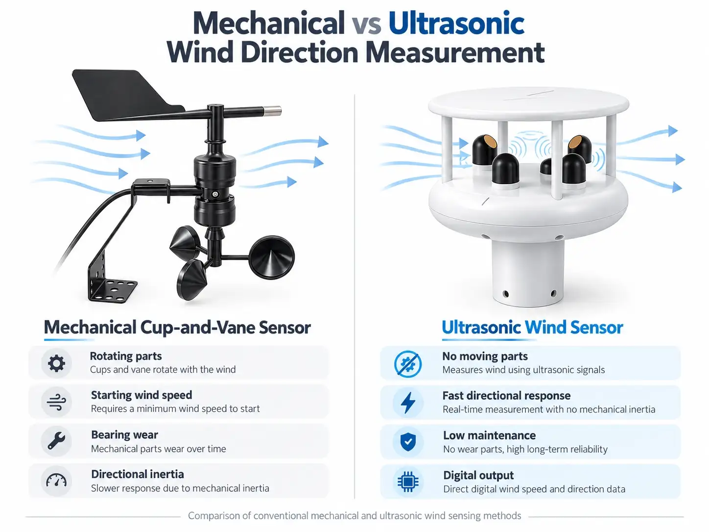
A conventional mechanical wind direction sensor usually consists of a tail vane, a rotating shaft, and a directional sensing mechanism.
Aerodynamic forces align the vane with the airflow.
This relatively simple principle is widely used in meteorological instruments, but its measurement performance depends on several interacting mechanical characteristics.
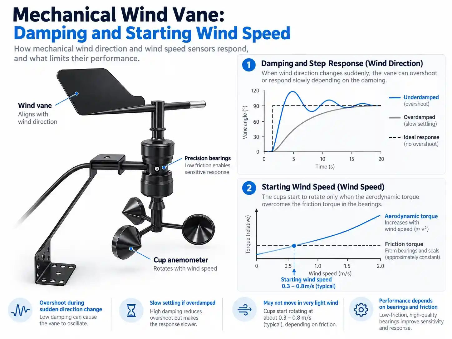
2.1 Damping Ratio and Directional Overshoot
The damping ratio describes how a mechanical system responds to movement and returns toward equilibrium.
When wind direction changes suddenly, the vane may rotate beyond the new equilibrium position before settling.
Insufficient damping can cause:
- Overshoot following abrupt wind direction changes
- Repeated oscillation around the actual wind direction
- Increased variation in instantaneous readings
- Difficulty obtaining stable directional measurements
Excessive damping produces a different problem.
The vane may respond too slowly when wind direction changes.
Therefore, mechanical wind vane design involves balancing responsiveness against oscillation and overshoot.
A single damping parameter cannot independently guarantee both fast response and stable measurements.
2.2 Starting Wind Speed and Mechanical Friction
A mechanical vane requires an aerodynamic force large enough to overcome resistance in the shaft and bearings.
The balance between aerodynamic torque and friction determines whether the vane begins moving.
Some conventional mechanical wind vanes have starting thresholds in the approximate range of 0.3–0.8 m/s, depending on their construction.
This range is illustrative rather than a universal specification.
Below the instrument’s starting threshold, the vane may remain stationary even though light airflow is present.
Such conditions may occur during:
- Stable nighttime weather
- Low-wind conditions in valleys
- Sheltered environmental monitoring locations
- Weak airflow in specific local microclimates
Mechanical cup anemometers also have starting and dynamic-response characteristics, although their specific behavior differs from that of wind vanes.
For monitoring applications involving frequent low-wind conditions, these mechanical limitations should be considered during instrument selection.
2.3 Mechanical Wear and Long-Term Directional Drift
Mechanical wind sensors contain moving components.
Long-term exposure may introduce additional measurement problems through bearing wear, contamination, corrosion, or ice formation.
For example, increased shaft friction can change how a vane responds to weak airflow.
Mechanical sticking can also create a misleading operating condition.
A vane may stop moving because of bearing resistance or icing while its electronic output continues reporting an unchanged direction.
If the monitoring system does not include suitable diagnostic checks, this frozen reading may appear valid.
Engineers should therefore consider both initial accuracy and long-term mechanical behavior when evaluating a conventional wind direction sensor.
3. How Does an Ultrasonic Anemometer Measure Wind Direction?
An ultrasonic anemometer uses acoustic measurement principles rather than a rotating wind vane or cup assembly.
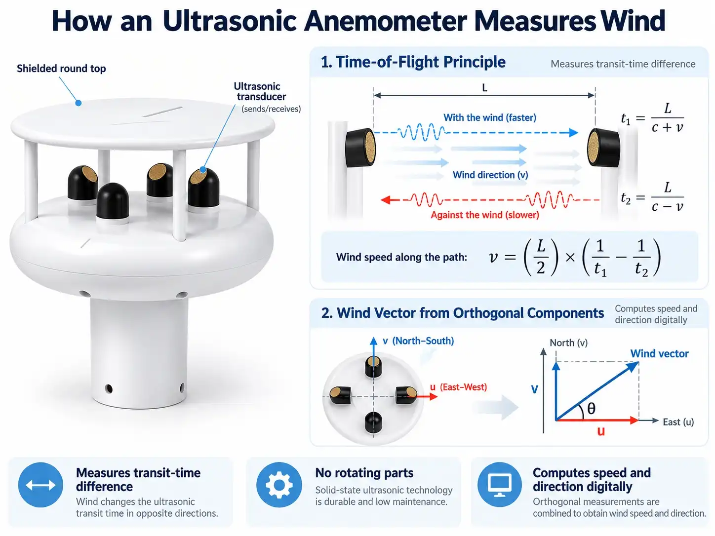
Its fundamental operating principle is based on the difference in ultrasonic signal travel time along defined measurement paths.
3.1 Ultrasonic Time-of-Flight Measurement
Consider two ultrasonic transducers separated by a distance L.
One signal travels in the same direction as the airflow, while another travels against it.
For a simplified measurement path:
- Downwind travel time: t₁ = L / (c + v)
- Upwind travel time: t₂ = L / (c − v)
Where:
- L is the acoustic path length.
- c is the speed of sound.
- v is the wind velocity component along the acoustic path.
- t₁ and t₂ are the corresponding travel times.
Combining the two expressions gives:
v = (L / 2) × (1/t₁ − 1/t₂)
This relationship allows the instrument to calculate the wind velocity component along the measurement path.
The bidirectional measurement also helps separate the wind-related contribution from the acoustic propagation speed in this idealized model.
3.2 Measuring Horizontal Wind Components
A two-dimensional ultrasonic wind sensor measures airflow along multiple acoustic paths.
Using appropriately arranged measurement paths, the instrument reconstructs two horizontal wind components.
These components are commonly represented as u and v.
The horizontal wind speed is:
V = √(u² + v²)
Wind direction is calculated from the horizontal components using an appropriate four-quadrant inverse tangent function.
The final calculation must account for the instrument’s coordinate system and the meteorological convention that wind direction indicates where the wind originates.
Unlike a mechanical vane, this measurement method does not depend on a rotating shaft reaching aerodynamic equilibrium.
3.3 Why the Absence of Moving Parts Matters
Ultrasonic wind sensors eliminate several mechanical limitations associated with traditional wind instruments.
These include mechanical bearing friction, rotating-component wear, and vane inertia.
As a result, ultrasonic technology is especially relevant to installations requiring frequent directional measurements or long-term outdoor operation.
However, a sensor without moving parts is not automatically free from measurement errors.
Potential influences still include:
- Acoustic-path obstruction or contamination
- Flow distortion caused by the sensor structure
- Installation orientation
- Environmental exposure and ice accumulation
- Signal processing and averaging methods
Proper installation, configuration, and maintenance remain important.
For demanding fixed-site applications, the JW-IoT High-Precision Ultrasonic Wind Speed and Direction Sensor offers a two-dimensional ultrasonic measurement solution with industrial communication interfaces and an available heating system.
4. Mechanical vs. Ultrasonic Wind Sensors: Dynamic Response
Wind direction does not always change gradually.
A monitoring instrument may encounter rapid changes associated with turbulence, local airflow disturbances, or changing weather conditions.
A simplified example is a sudden wind direction change from 0° to 90°.
Different sensing technologies respond differently.
4.1 Conventional Mechanical Wind Vane
A lightly damped mechanical vane may rotate past the new direction and oscillate before settling.
For some mechanical designs, directional overshoot can be substantial.
The source material illustrates an example in which overshoot may reach approximately 20°–30° following a 90° directional change.
This should not be interpreted as a universal result for all mechanical wind vanes.
Actual behavior depends on vane geometry, damping, friction, wind speed, and construction.
4.2 More Heavily Damped Mechanical Wind Vane
Increasing damping can reduce oscillation.
However, the instrument may require additional time to reach the new direction.
A more stable response therefore does not necessarily mean a faster response.
4.3 Ultrasonic Wind Direction Measurement
An ultrasonic sensor does not need to rotate toward the airflow.
Instead, it measures the effect of airflow on acoustic transmission and calculates wind components.
This removes mechanical rotational delay from the measurement process.
Nevertheless, the actual response displayed by a monitoring system depends on the instrument’s sampling interval, internal filtering, output frequency, and downstream processing.
A high output frequency alone does not establish the complete dynamic response of a wind monitoring system.
For projects involving rapidly changing airflow, engineers should examine both the measurement principle and the complete data acquisition chain.
5. Wind Direction Averaging: Why the Wrong Algorithm Can Produce a 180° Error
One of the most important sources of wind direction errors occurs after the measurement has already been collected.
The problem lies in how angular data is processed.
5.1 Why Arithmetic Averaging Fails
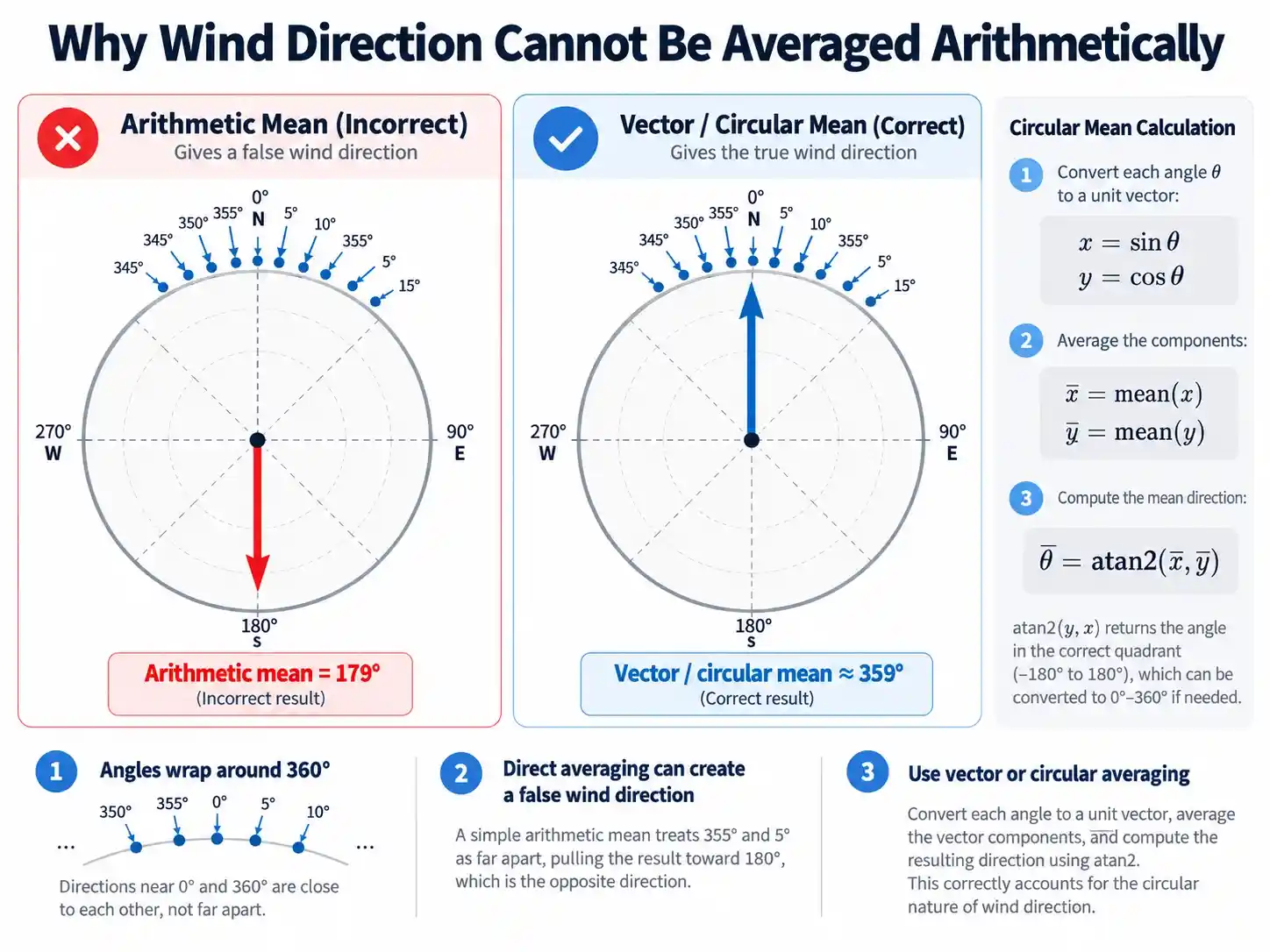
Imagine a wind direction sensor recording ten observations:
345°, 350°, 355°, 0°, 5°, 10°, 355°, 350°, 5°, and 15°.
All observations are concentrated near north.
Ordinary arithmetic gives:
(345 + 350 + 355 + 0 + 5 + 10 + 355 + 350 + 5 + 15) / 10
= 179°
This result indicates almost southerly wind.
Yet none of the observations represents wind from the south.
The problem occurs because angles wrap around at 360°.
5.2 Circular Averaging of Wind Direction
A more appropriate method for averaging directional angles is circular averaging.
Each measured angle θ is converted into two components:
x = sin θ
y = cos θ
The components are then averaged:
x̄ = Σsin θᵢ / n
ȳ = Σcos θᵢ / n
The average direction is reconstructed using:
θ̄ = atan2(x̄, ȳ)
The result is converted to the range 0°–360°.
For the ten observations above, the circular mean is approximately 359°.
This agrees with the actual distribution of measurements around north.
The use of a four-quadrant inverse tangent is important because an ordinary single-argument arctangent cannot independently identify every compass quadrant.
5.3 When Wind Speed Weighting Is Necessary
Circular averaging treats each directional observation with equal weight.
For meteorological vector averaging, wind speed can also be incorporated.
A wind vector has both magnitude and direction.
Using the meteorological direction-from convention, the corresponding horizontal flow components can be written as:
uᵢ = −Vᵢ sin θᵢ
vᵢ = −Vᵢ cos θᵢ
Where Vᵢ is the wind speed associated with each directional observation.
The average components are:
ū = Σuᵢ / n
v̄ = Σvᵢ / n
The resulting vector mean speed is:
V̄_vector = √(ū² + v̄²)
The mean direction is reconstructed from the averaged components, taking the direction-from convention into account.
This approach is particularly relevant when wind speed varies significantly between observations.
5.4 Opposing Wind Directions
Consider another measurement sequence:
- Eight observations from east, at 90°
- Eight observations from west, at 270°
- Equal wind speeds for all observations
Ordinary arithmetic produces:
(8 × 90° + 8 × 270°) / 16 = 180°
This falsely suggests a southerly prevailing direction.
Vector averaging produces a different result.
The eastward and westward contributions cancel.
The resulting mean wind vector has zero magnitude, meaning there is no uniquely defined resultant direction.
This does not mean the air was stationary during every observation.
It means the opposing wind vectors cancel over the averaging period.
If wind speeds are unequal, the stronger contributions will influence the resulting vector direction.
5.5 Circular Mean vs. Vector Mean
Circular and vector averaging answer related but different questions.
Circular averaging describes the central direction of angular observations.
Wind-speed-weighted vector averaging describes the resultant airflow vector.
Neither should be confused with the arithmetic average of scalar wind speeds.
For reliable monitoring, the selected algorithm should correspond to the reporting objective.
The system should also identify periods in which the resultant vector is too small for a meaningful mean direction to be assigned.
6. Wind Direction Accuracy, Resolution, and Measurement Conditions
Wind sensor specifications frequently include a direction accuracy value and a direction resolution value.
These specifications describe different characteristics.
6.1 Wind Direction Accuracy
Accuracy describes how closely an instrument’s reported wind direction corresponds to a reference measurement under specified conditions.
For example, a stated accuracy of ±3° indicates an allowable directional error according to the relevant manufacturer’s test conditions.
It should not be interpreted as a universal performance guarantee under every possible wind speed or installation condition.
6.2 Wind Direction Resolution
Resolution describes the smallest reported change or increment in the measurement output.
A resolution of 1° does not mean the instrument has an accuracy of ±1°.
An instrument may report wind direction in one-degree increments while having a larger specified accuracy tolerance.
6.3 The Importance of Wind Speed Conditions
Some ultrasonic wind sensor specifications explicitly state the wind speed conditions under which directional accuracy applies.
For example, the JW-WDSS2(HY05) reference specification identifies a wind direction accuracy of ±3° when wind speed is at least 1 m/s.
This qualification is important.
At very low wind speeds, the horizontal wind vector becomes small and the directional measurement may be more sensitive to noise and disturbances.
When comparing products, engineers should examine the complete accuracy statement rather than focusing only on the numerical value.
6.4 Output Frequency Is Not Accuracy
Output frequency describes how frequently measurement information is provided.
A sensor operating at 10 Hz can produce more frequent observations than one operating at 1 Hz.
However, a higher reporting frequency does not automatically mean better accuracy.
It may improve the temporal detail available to the monitoring system, subject to the sensor’s actual response and processing characteristics.
For long-term wind observations, both reporting frequency and averaging period should be selected according to project requirements.
7. How Installation Orientation Affects Wind Direction Data
Correct installation is essential for obtaining meaningful wind direction measurements.
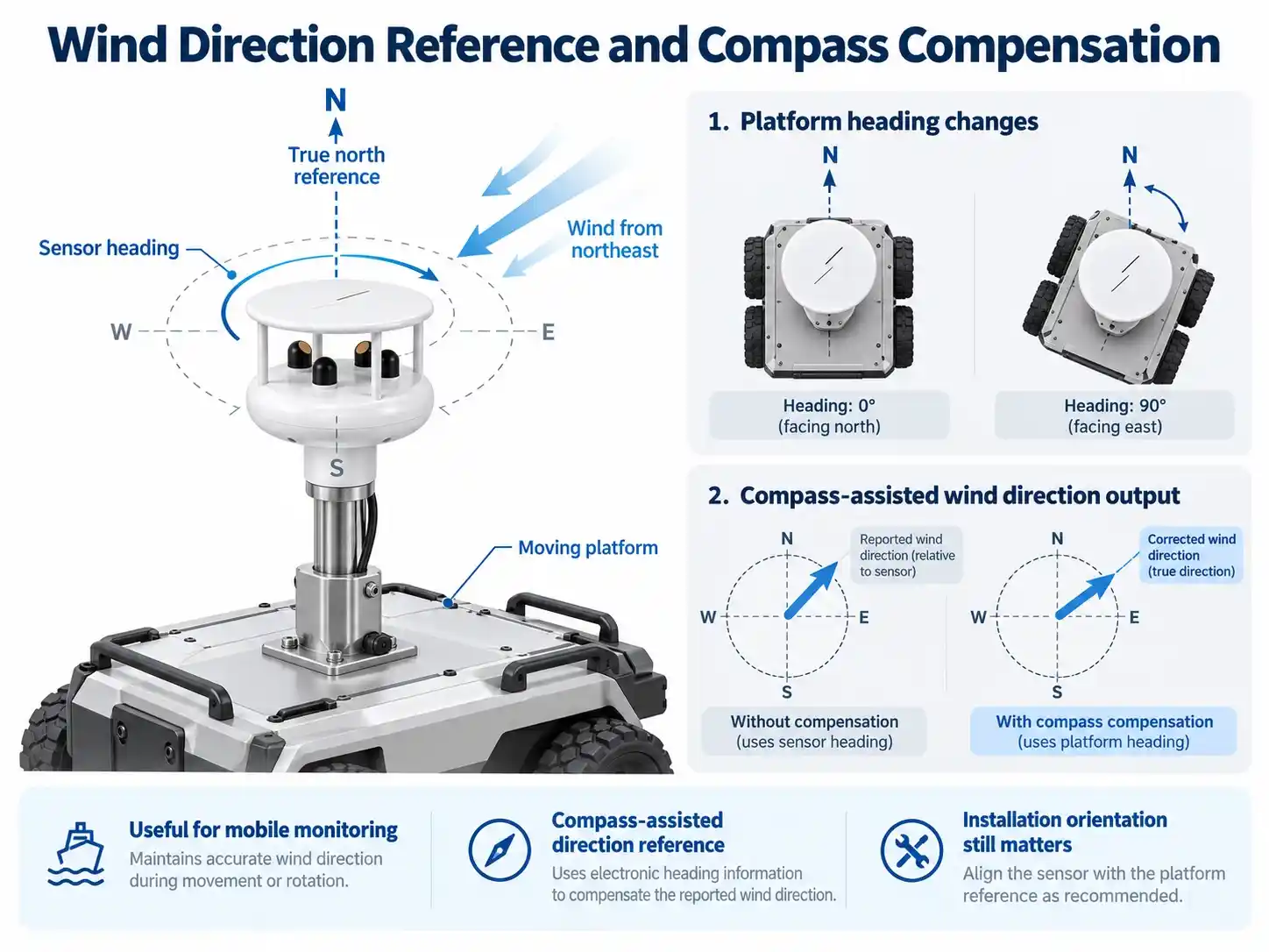
7.1 True North Reference
Meteorological wind direction is normally referenced to geographical north.
For a fixed sensor, its physical reference axis must be correctly aligned or its angular offset must be accounted for in data processing.
A consistent installation offset can shift the entire direction dataset.
For example, a 10° reference misalignment can produce a systematic error even if the sensing element itself is operating within its stated accuracy.
7.2 Why Stable Data Can Still Be Wrong
Systematic installation errors are often difficult to identify from time-series plots alone.
A sensor with a fixed directional offset may still generate:
- Smooth measurement curves
- Repeatable daily wind patterns
- Stable output values
- No communication alarms
The absence of unusual fluctuations does not prove that the wind direction reference is correct.
Installation records and directional verification should therefore form part of sensor commissioning.
7.3 Wind Sensors with Integrated Electronic Compasses
Some applications involve platforms whose orientation may change.
In these situations, a fixed geographical alignment cannot always be assumed.
The JW-WDS2 Compass-Integrated Ultrasonic Anemometer combines ultrasonic wind measurement with a three-axis electronic compass and motion-related sensing.
The compass provides heading information that can support directional interpretation when the sensor’s orientation changes.
However, heading information alone does not fully compensate for platform movement.
For vehicle-mounted or other moving applications, accurate interpretation may also require consideration of platform velocity, tilt, and airflow distortion.
Magnetic interference and compass calibration must also be considered.
8. Comparing JW-IoT Ultrasonic Wind Sensor Configurations
Different ultrasonic anemometer designs address different installation and measurement requirements.
The following comparison is based on the referenced product descriptions and the supplied technical material.
| Parameter | JW-WDSS2(HY05) | JW-WDS2 | JW-W3DS2(HY06) |
| Sensor type | 2D ultrasonic | 2D ultrasonic with compass | 3D ultrasonic |
| Wind direction range | 0–359° | 0–360° equivalent | 0–359° |
| Direction accuracy | ±3° at V ≥ 1 m/s | ±3° | ±3° |
| Direction resolution | 1° | 1° | 1° |
| Standard output | 1 Hz | Confirm selected configuration | 1 Hz |
| Optional frequency | 4 Hz | Confirm selected configuration | 2/5/10 Hz |
| Heating | Up to 120 W | Optional | Not specified |
| Approximate weight | 1.13 kg | 0.36 kg | 0.11 kg |
| Main advantage | Harsh-environment monitoring | Orientation information | Three-dimensional wind measurement |
These products should not be selected solely according to their wind direction accuracy figures.
Their sensing capabilities, environmental protection, installation requirements, communication interfaces, and data-processing needs are also important.
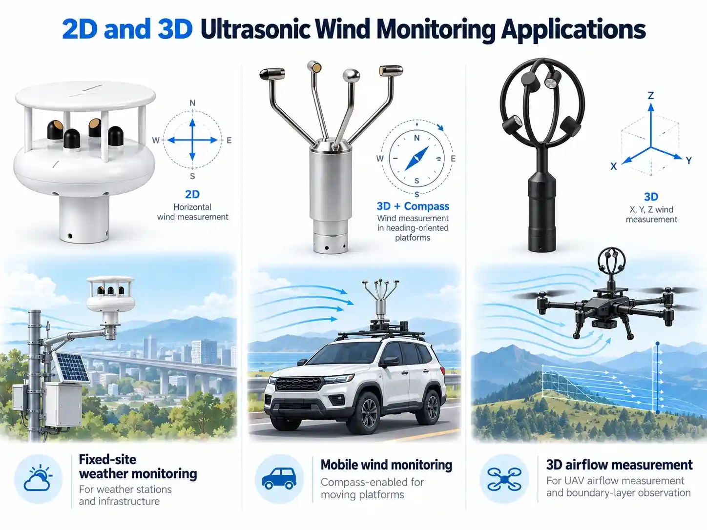
8.1 High-Precision Ultrasonic Wind Sensor for Fixed Installations
The JW-WDSS2(HY05) High-Precision Ultrasonic Wind Speed and Direction Sensor is designed for demanding outdoor installations.
Its published features include:
- Wind speed range of 0–60 m/s
- Wind direction range of 0–359°
- Wind direction accuracy of ±3°
- RS485/RS232 communication options
- MODBUS support
- Stainless-steel and aluminum-alloy construction
- Heating capability up to 120 W
- IP65 protection
These characteristics make it relevant to fixed meteorological stations, transportation infrastructure, coastal monitoring, and industrial weather observation.
Its heating capability is particularly important when evaluating installations exposed to low temperatures and potential ice accumulation.
8.2 Ultrasonic Anemometer with Compass for Mobile Monitoring
The JW-WDS2 Ultrasonic Anemometer with Compass focuses on applications where orientation information is important.
Its integrated three-axis compass and acceleration sensing distinguish it from conventional fixed-orientation ultrasonic anemometers.
The compact design is relevant to mobile environmental monitoring and temporary weather observation systems.
For moving platforms, integrators should verify how heading, tilt, platform motion, and wind vector data are combined.
8.3 3D Ultrasonic Wind Sensor for UAV Airflow Measurement
The JW-W3DS2(HY06) 3D Ultrasonic Wind Sensor is designed for applications requiring three-dimensional airflow information.
Unlike a conventional 2D wind sensor, the 3D configuration provides horizontal and vertical wind components.
Its published specifications include:
- Wind speed measurement range of 0–50 m/s
- Wind direction range of 0–359°
- Wind direction accuracy of ±3°
- Wind speed accuracy of ±2%
- Standard 1 Hz output, with 2 Hz, 5 Hz, and 10 Hz options
- RS485, RS232, and SDI-12 interface options
- Approximately 110 g instrument weight
The sensor is relevant to UAV airflow observation, atmospheric research, boundary-layer measurements, and compact environmental monitoring platforms.
For UAV installations, mounting geometry and airflow disturbances produced by the aircraft must be evaluated.
Three-dimensional measurement capability does not automatically eliminate rotor-induced airflow interference.
9. Practical Guidelines for Improving Wind Direction Measurement Reliability
Reliable wind data depends on the complete monitoring system, not only the measurement element.
9.1 Confirm the Directional Reference
Before commissioning a wind direction sensor, verify its reference orientation.
For fixed installations, confirm geographical alignment.
For systems with electronic compasses, verify compass configuration and potential magnetic interference.
9.2 Use Appropriate Wind Direction Averaging
Avoid directly applying arithmetic averaging to wind direction angles.
Choose circular averaging or wind vector averaging according to the intended meteorological calculation.
Clearly distinguish scalar mean wind speed from vector mean wind speed.
9.3 Establish Low-Wind Data Validity Rules
Wind direction values recorded during near-calm conditions may not be representative.
A monitoring system should identify these conditions using an appropriate wind speed threshold or data quality criterion.
The applicable threshold should be based on the sensor specification and the project’s observation requirements.
9.4 Monitor Data Quality Over Time
Long-term monitoring systems should examine repeated directional readings, unrealistic patterns, communication interruptions, and other indicators of potentially invalid measurements.
A constant wind direction reading is not necessarily an equipment fault, but persistent values should be assessed in relation to wind speed and surrounding conditions.
9.5 Evaluate Environmental Protection
Mechanical wear is not the only long-term reliability concern.
Ultrasonic sensor performance can also be influenced by environmental exposure, contamination, ice accumulation, and installation conditions.
For freezing environments, confirm whether the sensor includes an appropriate heating configuration.
The available electrical power should be sufficient for the selected operating mode.
9.6 Verify Data Logger Compatibility
Before connecting a wind sensor to a data acquisition system, confirm the required communication interface and data format.
Possible considerations include:
- RS485 or RS232 communication
- SDI-12 compatibility
- MODBUS configuration
- Measurement update interval
- Wind direction reference convention
- Averaging and reporting settings
- Invalid-data handling
The integration process should preserve both the measured data and its quality information wherever possible.
10. Frequently Asked Questions About Wind Direction Measurement
What instrument measures wind direction?
A wind vane is the traditional instrument for measuring wind direction. An ultrasonic anemometer can also measure wind direction by calculating airflow components from ultrasonic signal travel times.
Why is wind direction difficult to average?
Wind direction is a circular variable. Ordinary arithmetic averaging can produce incorrect results near the 0°/360° boundary. Circular averaging and vector averaging address this problem using directional components.
Can an ultrasonic anemometer measure wind direction at zero wind speed?
An ultrasonic anemometer does not require mechanical rotation to begin measuring airflow. However, when wind speed is zero, there is no physically defined horizontal wind direction. Near-calm readings should therefore be interpreted cautiously.
Is a 1° wind direction resolution the same as ±1° accuracy?
No. Resolution describes the smallest output increment, while accuracy describes measurement deviation relative to a reference under specified conditions.
Why might a wind direction sensor always report the same angle?
Possible explanations include persistent wind from one direction, installation problems, mechanical sticking, sensor faults, or processing issues. The wind speed data and instrument condition should be checked before drawing conclusions.
What is the advantage of a 3D ultrasonic wind sensor?
A 3D ultrasonic sensor measures three airflow components, including the vertical component. This makes it relevant to atmospheric research, turbulence studies, and UAV airflow monitoring where horizontal wind measurements alone may be insufficient.
How can wind direction errors be reduced?
Key measures include verifying installation alignment, using suitable averaging algorithms, checking low-wind validity, selecting an appropriate sensor design, and maintaining the monitoring system.
Conclusion
Accurate wind direction measurement requires more than a sensitive measuring element.
The reliability of the final data depends on three connected factors: the instrument’s sensing principle, the measurement installation, and the algorithms used to process directional observations.
Mechanical wind vanes are influenced by friction, damping, starting wind speed, and component condition.
Ultrasonic anemometers remove the need for rotating measurement components and provide an alternative method based on acoustic travel-time differences.
Nevertheless, ultrasonic instruments still require correct installation, appropriate data processing, and careful interpretation of accuracy specifications.
For engineers developing weather monitoring systems, attention should be given to wind direction accuracy under specified operating conditions, output frequency, environmental requirements, and system integration.
JW-IoT offers multiple ultrasonic wind sensor configurations for fixed weather stations, mobile environmental monitoring, and three-dimensional airflow measurement.
Explore JW-IoT Wind Monitoring Solutions:
- High-Precision Ultrasonic Wind Speed and Direction Sensor
- Ultrasonic Anemometer with Compass for Mobile Wind Monitoring
- 3D Ultrasonic Wind Sensor for UAV Airflow Measurement
- Browse All JW-IoT Wind Sensors
For sensor selection, technical specifications, and system integration requirements, contact JW-IoT to discuss your wind monitoring application.