+86 13520127780
  info@jingelway.com








How LoRaWAN Nodes Streamline PV Monitoring in Large Solar Farms
Release time: 2026-08-16
Large utility-scale solar farms may cover hundreds or even thousands of hectares. Across such a large area, solar irradiance, PV module temperature, wind conditions, rainfall, and local environmental conditions are rarely identical at every location.
A single weather station can provide useful reference data, but it may not represent conditions across the entire plant.
This is why many large PV projects are moving toward distributed monitoring architectures, where multiple sensor nodes are installed across different array blocks and connected to a central monitoring system.
A LoRaWAN PV monitoring node provides one practical way to build this type of network without running long communication cables between every monitoring point.
LoRaWAN is a Low Power Wide Area Network technology designed for long-range, low-data-rate IoT communications. Its network architecture typically connects field end devices to one or more gateways, which then forward the data through IP networks to a network server or application platform.
For solar farms, this architecture makes it possible to collect distributed irradiance, module temperature, weather, and equipment-status data while simplifying communication infrastructure.
Why Large Solar Farms Need Distributed Monitoring?
Environmental conditions inside a large photovoltaic plant can vary significantly from one zone to another.
Differences may be caused by:
- cloud movement
- terrain elevation
- module orientation
- shading
- dust accumulation
- wind exposure
- local rainfall
- surface temperature
- vegetation
- distance between PV blocks
If a plant relies on only one environmental monitoring point, operators may have difficulty determining whether reduced power output is caused by equipment problems or simply by localized weather conditions.
A distributed monitoring network can provide data from several representative locations.
For example, separate monitoring nodes may be installed in:
- different inverter blocks
- different terrain elevations
- east and west sections of the plant
- areas with different module orientations
- locations exposed to different dust conditions
- representative meteorological zones
Each node can collect environmental data and transmit it to a central monitoring system.
This creates a more representative environmental dataset for performance analysis.
JW-IoT’s existing Solar PV Monitoring System with IoT Automation is designed around this type of distributed architecture, integrating solar radiation, weather, PV module, electrical, and communication data for centralized plant monitoring.
The Challenge of Wired Sensor Deployment in Large PV Plants
RS485 remains one of the most common communication methods for industrial sensors and PV monitoring equipment.
For monitoring points located close to a data logger or weather station, wired RS485 communication is often an excellent option.
However, connecting many monitoring points across a very large solar farm can create several practical challenges.
Long cable distances
When sensors are distributed over large distances, communication cables may need to cross:
- PV array rows
- access roads
- drainage channels
- tracker structures
- inverter blocks
- underground cable routes
This increases installation complexity.
Additional trenching and conduit
Long wired communication networks may require additional:
- trenches
- conduits
- junction boxes
- cable trays
- lightning protection
- surge protection
The communication network can therefore become a significant part of the monitoring-system installation.
Difficult expansion
A solar farm may initially require five environmental monitoring points but later expand to ten or twenty.
With a fully wired architecture, adding new points may require new cable routes.
A wireless node can often be installed with fewer changes to the existing communication infrastructure.
Maintenance complexity
Communication faults in long cable networks can be difficult to locate.
Possible causes include:
- damaged cables
- water ingress
- loose terminals
- electromagnetic interference
- lightning damage
- damaged underground conduits
For distributed measurements that transmit only small packets of sensor data, wireless communication can therefore provide an attractive alternative.
What Is a LoRaWAN PV Monitoring Node?
A LoRaWAN PV monitoring node is a field data-acquisition device that collects measurements from one or more PV monitoring sensors and transmits the data wirelessly through a LoRaWAN network.
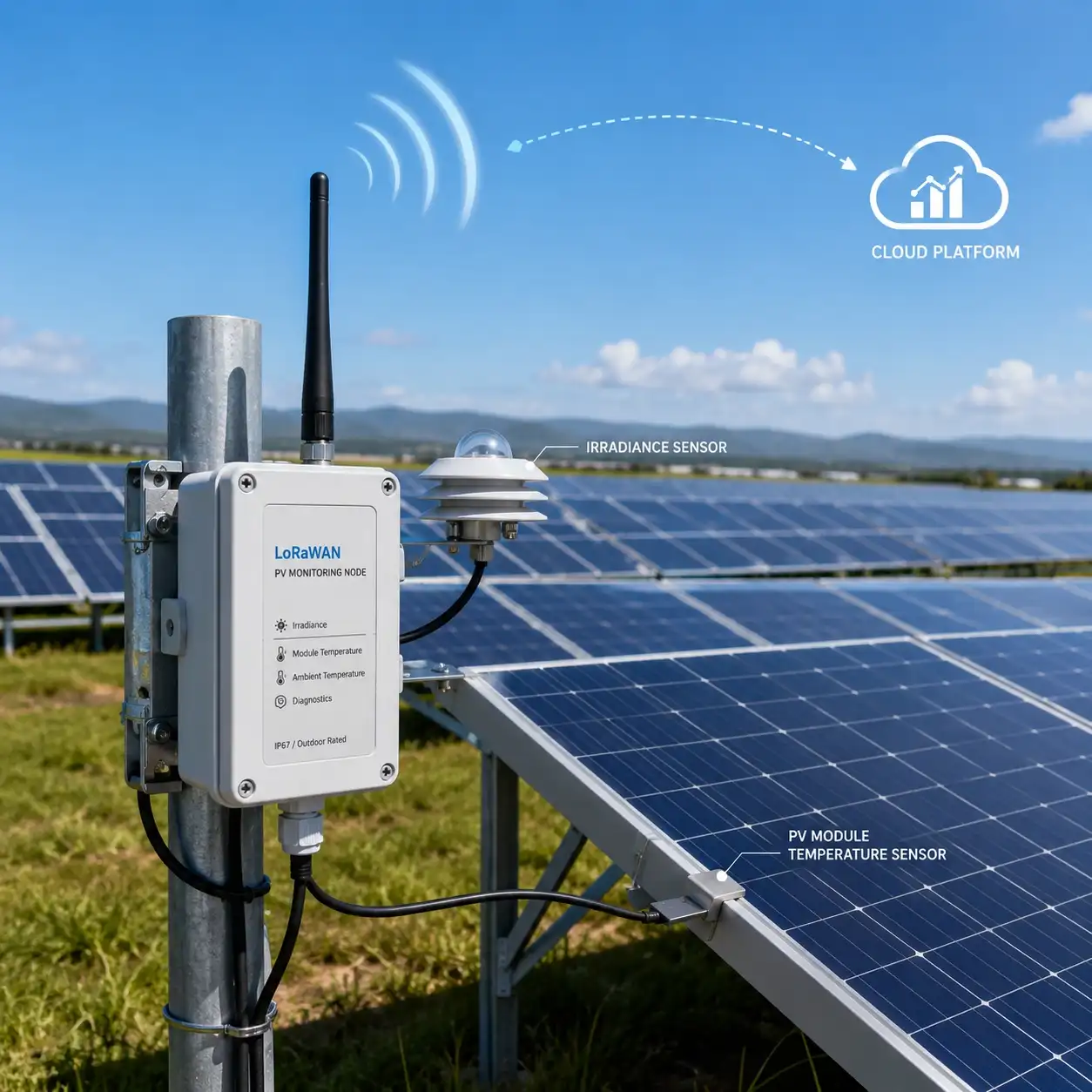
A typical node may include:
Environmental sensors
↓
RS485 / Modbus or analog interface
↓
LoRaWAN sensor node / RTU
↓
LoRaWAN gateway
↓
4G / Ethernet backhaul
↓
Cloud platform / SCADA / EMS
Instead of connecting every field sensor directly to a central control room, each monitoring node becomes a local data-acquisition point.
The LoRaWAN gateway functions as the bridge between the wireless sensor network and the IP-based network. In the standard LoRaWAN star-of-stars topology, gateways relay packets between end devices and the central network infrastructure.
This architecture is particularly useful when the data consists of relatively small sensor measurements transmitted periodically rather than continuous high-bandwidth data streams.
How LoRaWAN Works in PV Monitoring?
Consider a 300 MW solar farm divided into multiple PV blocks.
Instead of installing a single central weather station, the project might deploy several environmental monitoring points.
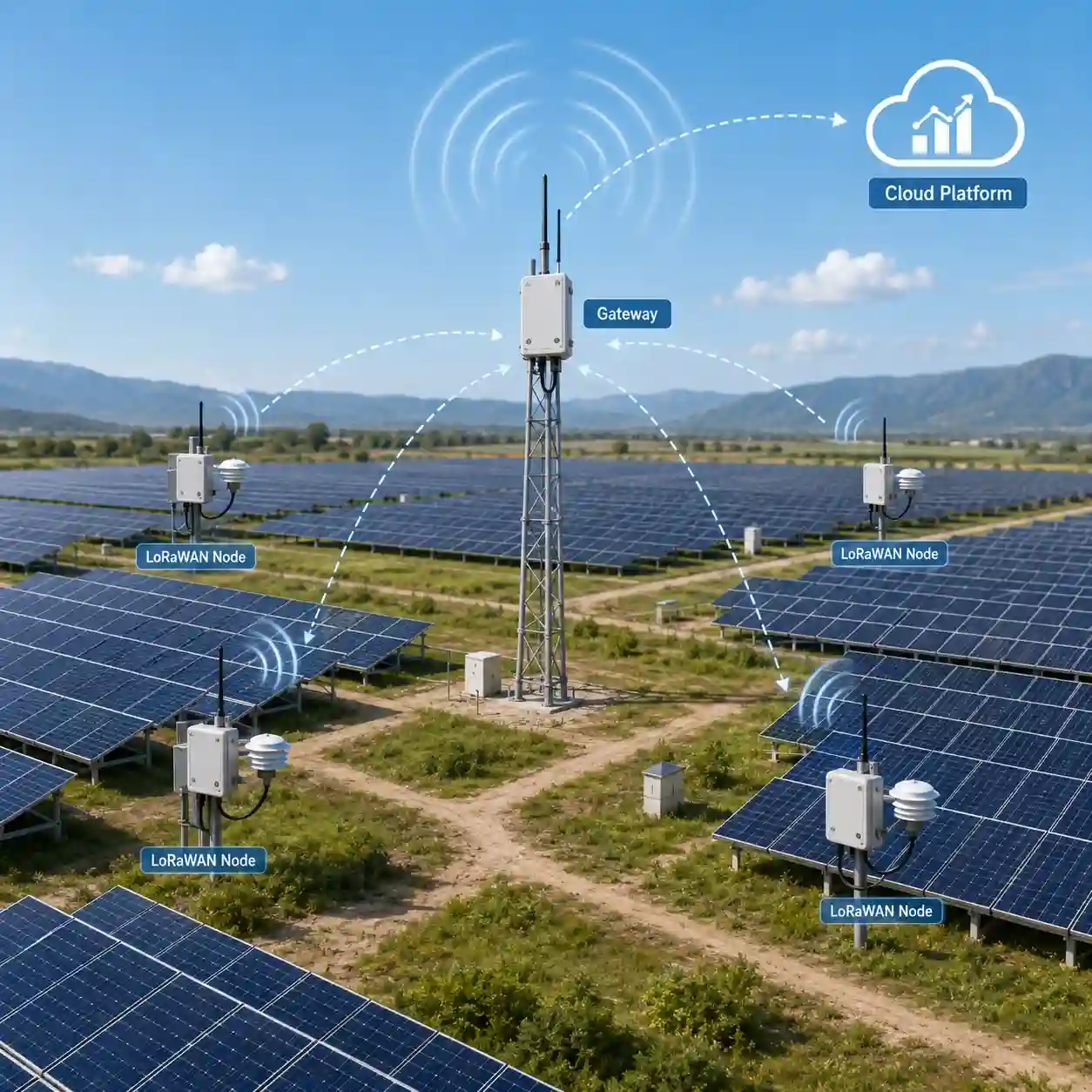
For example:
PV Block A
- irradiance sensor
- module temperature sensor
- ambient temperature and humidity sensor
PV Block B
- irradiance sensor
- module temperature sensor
PV Block C
- irradiance sensor
- wind sensor
Central weather station
- pyranometer
- air temperature
- humidity
- wind speed
- wind direction
- rainfall
- atmospheric pressure
Each local monitoring point connects its sensors to a LoRaWAN node.
The node periodically sends measurements toward the LoRaWAN gateway.
The gateway then transfers the data to:
- a cloud monitoring platform
- plant SCADA
- energy management system
- O&M platform
- third-party IoT platform
JW-IoT’s existing solar PV monitoring architecture uses a similar model:
PV Sensors → Data Logger / IoT Controller → LoRaWAN / 4G Gateway → Cloud Server → Web / Mobile App → PV Performance Monitoring
The existing solution also supports MQTT and API integration for third-party systems.
Typical Sensors Connected to a LoRaWAN PV Monitoring Node
A monitoring node does not necessarily need to measure every environmental parameter.
The sensor combination should depend on the purpose of the monitoring point.
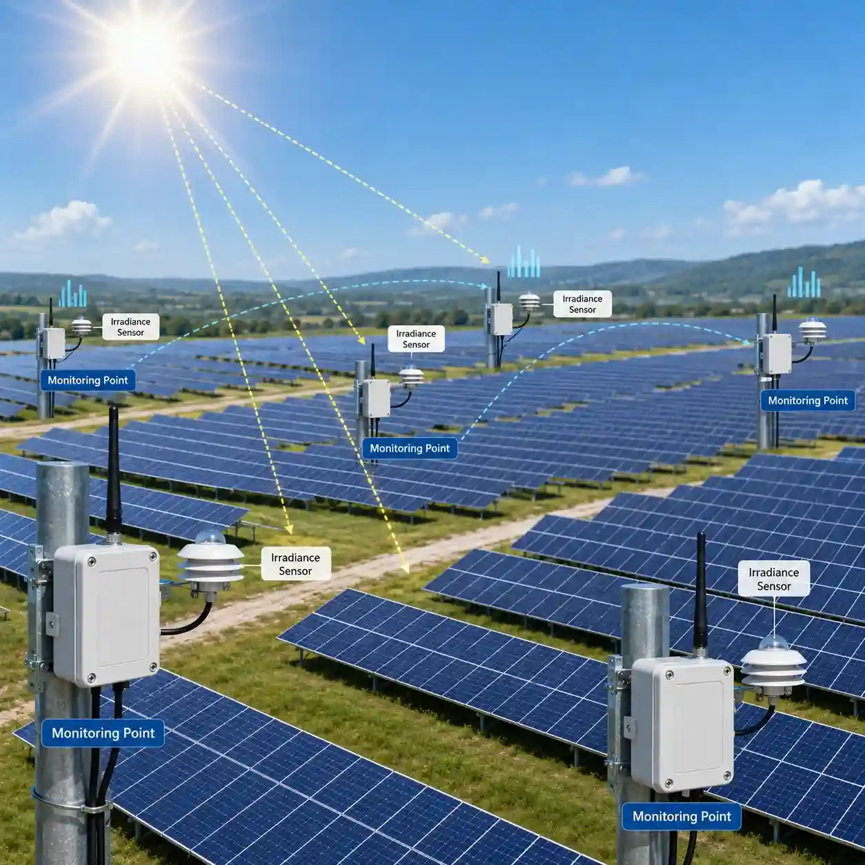
1. Solar Irradiance Sensor
Solar irradiance is one of the most important reference parameters for evaluating PV output.
Depending on the plant design, sensors may monitor:
- Global Horizontal Irradiance — GHI
- Plane-of-Array irradiance — POA
- reflected irradiance
- reference-cell irradiance
For high-accuracy meteorological or performance monitoring applications, a pyranometer may be used.
JW-IoT provides a Class A Pyranometer Solar Radiation Sensor designed for professional irradiance monitoring in photovoltaic applications.
Typical node configuration:
Irradiance Sensor
→ RS485 / Modbus
→ LoRaWAN Node
→ Gateway
→ PV Monitoring Platform
2. PV Module Temperature Sensor
PV module efficiency is strongly influenced by operating temperature.
Measuring module temperature helps operators compare environmental conditions with actual power generation.
Sensors are normally mounted on the rear surface of representative PV modules.
JW-IoT’s PV Module Temperature Sensors for Solar Plant Monitoring are designed specifically for measuring PV panel operating temperature.
Distributed module temperature monitoring can be especially valuable when a large farm contains:
- multiple module technologies
- different mounting structures
- different terrain conditions
- several tracker zones
- different ventilation conditions
Instead of assuming that one module temperature represents the whole site, operators can compare thermal conditions between zones.
3. Ambient Temperature and Humidity
Ambient air temperature provides important context for PV module temperature and system performance.
Humidity measurements can also help characterize site environmental conditions.
These parameters can be included either as individual sensors or as part of an integrated weather sensor.
4. Wind Speed and Wind Direction
Wind affects:
- module cooling
- dust movement
- soiling distribution
- tracker operation
- mechanical loading
- maintenance safety
Large PV plants located in desert or open terrain may therefore install wind monitoring at several representative locations.
Wind direction data can also help explain how dust moves across different PV blocks.
5. Rainfall
Rainfall affects solar-farm operation in several ways.
It can:
- remove dust from module surfaces
- influence soiling patterns
- affect maintenance access
- indicate storm conditions
- contribute to drainage risks
Distributed rainfall monitoring may be useful when the site covers a particularly large or topographically complex area.
6. Soiling Monitoring
PV soiling can vary across different sections of a solar farm.
For example, modules located near:
- unpaved roads
- agricultural land
- construction areas
- desert boundaries
- prevailing dust sources
may experience higher soiling rates than modules elsewhere.
Combining distributed soiling information with irradiance and wind data can provide better support for cleaning strategies.
Recommended Sensor Combinations
Different monitoring points can use different sensor configurations.
| Monitoring Point | Recommended Sensors | Typical Purpose |
| Irradiance Node | POA irradiance + module temperature | Compare local solar resource and module performance |
| Environmental Node | Temperature + humidity + wind | Local weather monitoring |
| Soiling Node | Irradiance + soiling sensor + wind | Cleaning and dust analysis |
| PV Block Node | Irradiance + module temperature | Block-level performance analysis |
| Main Weather Station | Irradiance + temperature + humidity + wind + rainfall + pressure | Plant reference meteorological data |
The objective is not to duplicate a complete weather station at every location.
Instead, the network should place the appropriate sensors where the data provides the greatest operational value.
LoRaWAN Gateway and Cloud Platform Architecture
A scalable solar-farm network normally contains four layers.
Layer 1 — Sensor Layer
Field sensors measure:
- irradiance
- PV module temperature
- ambient temperature
- humidity
- wind
- rainfall
- soiling
- other environmental parameters
Layer 2 — LoRaWAN Monitoring Node
The monitoring node collects sensor readings.
Depending on the sensor interface, the node may connect through:
- RS485
- Modbus RTU
- analog input
- pulse input
- digital input
For many PV applications, RS485 Modbus provides a practical interface between sensors and the local wireless node.
Layer 3 — LoRaWAN Gateway
Multiple LoRaWAN nodes communicate with one or more gateways.
The gateway then sends the monitoring data through an IP backhaul such as:
- Ethernet
- 4G LTE
- fiber network
- existing plant network
Using multiple gateways may also provide better site coverage and network redundancy depending on project layout.
LoRaWAN was designed as a scalable LPWA network architecture, and the LoRa Alliance describes deployments ranging from single-gateway installations to very large networks.
Layer 4 — Cloud, SCADA or EMS
The final destination may be:
- JW-IoT monitoring platform
- plant SCADA
- solar O&M platform
- energy management system
- private cloud
- customer IoT platform
Data can then be used for:
- real-time dashboards
- historical trends
- alarm management
- PV performance analysis
- environmental comparison
- maintenance planning
- multi-site management
For projects requiring a complete plant-level system, see the JW-IoT Solar PV Monitoring System.
Example Wireless PV Monitoring Architecture
A typical large-scale deployment might look like this:
Monitoring Zone 1
POA Irradiance + Module Temperature
↓
LoRaWAN Node
Monitoring Zone 2
POA Irradiance + Module Temperature
↓
LoRaWAN Node
Monitoring Zone 3
Wind + Temperature + Humidity
↓
LoRaWAN Node
Monitoring Zone 4
Soiling + Irradiance
↓
LoRaWAN Node
Main PV Weather Station
Pyranometer + Wind + Rain + Temperature + Humidity
↓
Data Logger / LoRaWAN Node
All wireless nodes
↓
LoRaWAN Gateway
↓
4G / Ethernet
↓
Cloud Platform / Network Server
↓
PV O&M Platform / SCADA / EMS
This type of hybrid architecture allows wired sensors to remain wired locally while replacing long-distance communication cables with LoRaWAN.
Why a Hybrid RS485 + LoRaWAN Architecture Often Makes Sense?
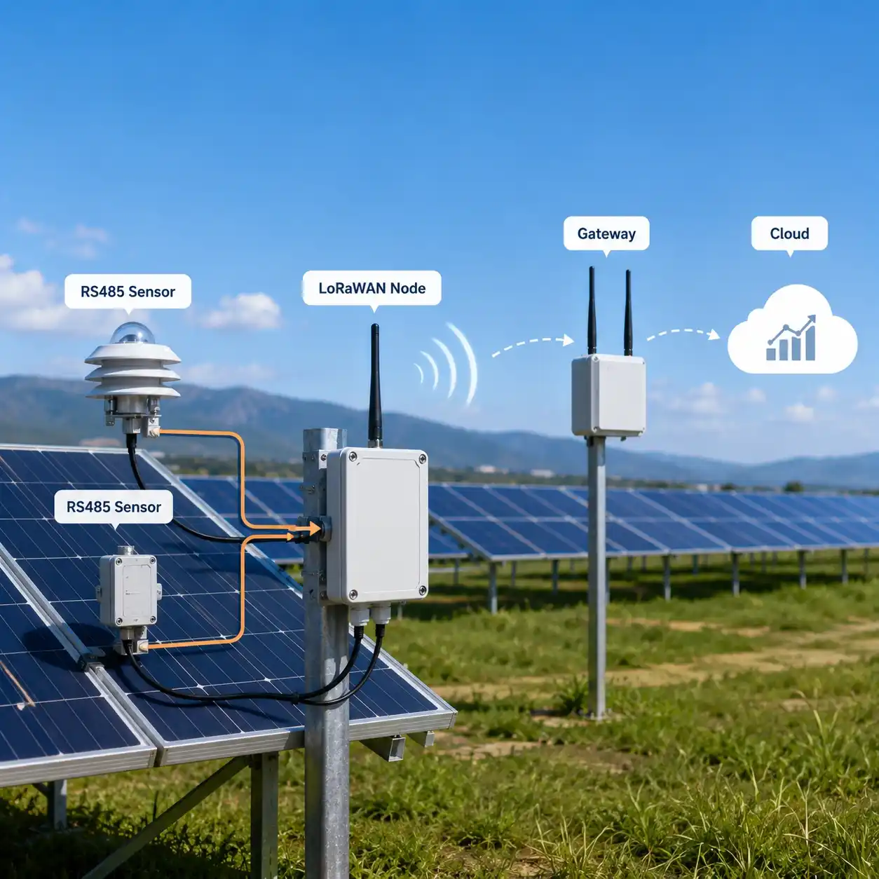
An important point is that LoRaWAN does not necessarily replace RS485.
In many PV projects, the two technologies work together.
Local level
RS485 connects:
Sensor → LoRaWAN node
Plant level
LoRaWAN connects:
Monitoring node → Gateway
Cloud level
4G, Ethernet or fiber connects:
Gateway → Server
This architecture combines the stability of industrial wired sensors with the flexibility of wireless field communication.
For example:
Class A Pyranometer → RS485 → LoRaWAN Node → LoRaWAN Gateway → 4G → Cloud
rather than:
Class A Pyranometer → several hundred meters of RS485 cable → central logger
The optimum architecture depends on plant layout, sensor density, terrain, communication coverage and existing infrastructure.
LoRaWAN vs 4G vs RS485 for PV Monitoring
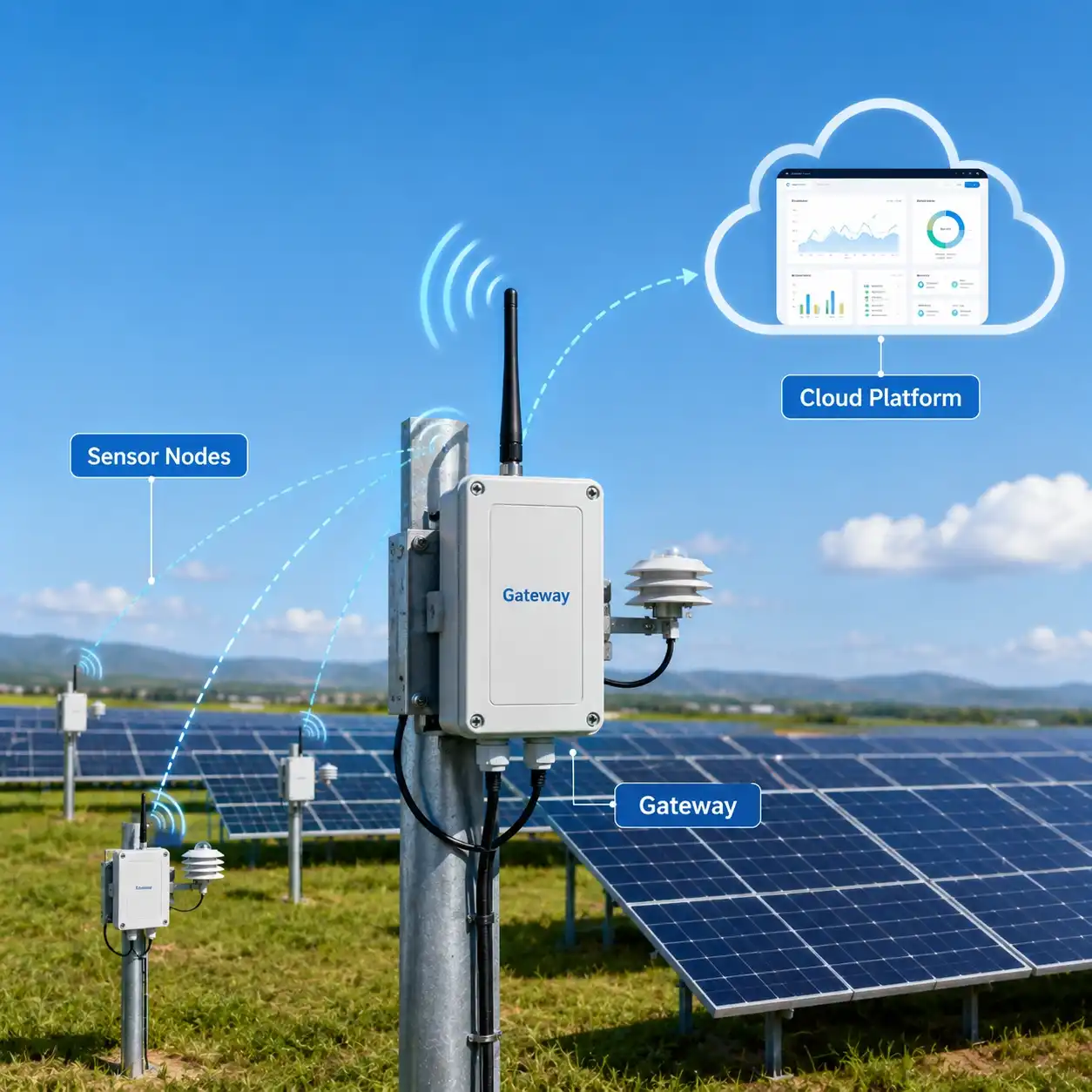
These communication technologies are not necessarily competitors.
Each performs a different role.
| Technology | Best Use in PV Monitoring |
| RS485 | Local sensor-to-controller communication |
| LoRaWAN | Distributed monitoring points across large PV farms |
| 4G LTE | Remote connection from gateway or station to cloud |
| Ethernet/Fiber | Fixed plant network and SCADA integration |
A common architecture therefore becomes:
RS485 sensors → LoRaWAN node → LoRaWAN gateway → 4G/Ethernet → cloud
JW-IoT’s PV monitoring solution also lists LoRaWAN for large solar farm monitoring points, 4G LTE for remote PV plants, RS485 Modbus for field equipment and Ethernet for plant-level systems.
Central Weather Station vs Distributed LoRaWAN Nodes
A useful PV monitoring network normally does not replace the main weather station with wireless nodes.
Instead, the two systems complement each other.
Central PV Weather Station
The primary weather station provides high-quality reference meteorological measurements.
A typical system may include:
- pyranometer
- POA irradiance
- module temperature
- air temperature
- humidity
- wind speed
- wind direction
- rainfall
- atmospheric pressure
JW-IoT’s Solar Weather Monitoring Station for Utility Photovoltaic Power Plants is designed for solar power plants, PV farms and other photovoltaic monitoring applications.
Distributed LoRaWAN Nodes
Secondary monitoring nodes can then provide localized measurements from selected areas.
For example:
Main Station:
Full meteorological reference
Node A:
POA irradiance + module temperature
Node B:
POA irradiance + module temperature
Node C:
Wind speed + wind direction
Node D:
Soiling + irradiance
This combination can deliver a much more representative picture of plant conditions than either architecture alone.
Recommended Deployment Model for Large Solar Farms
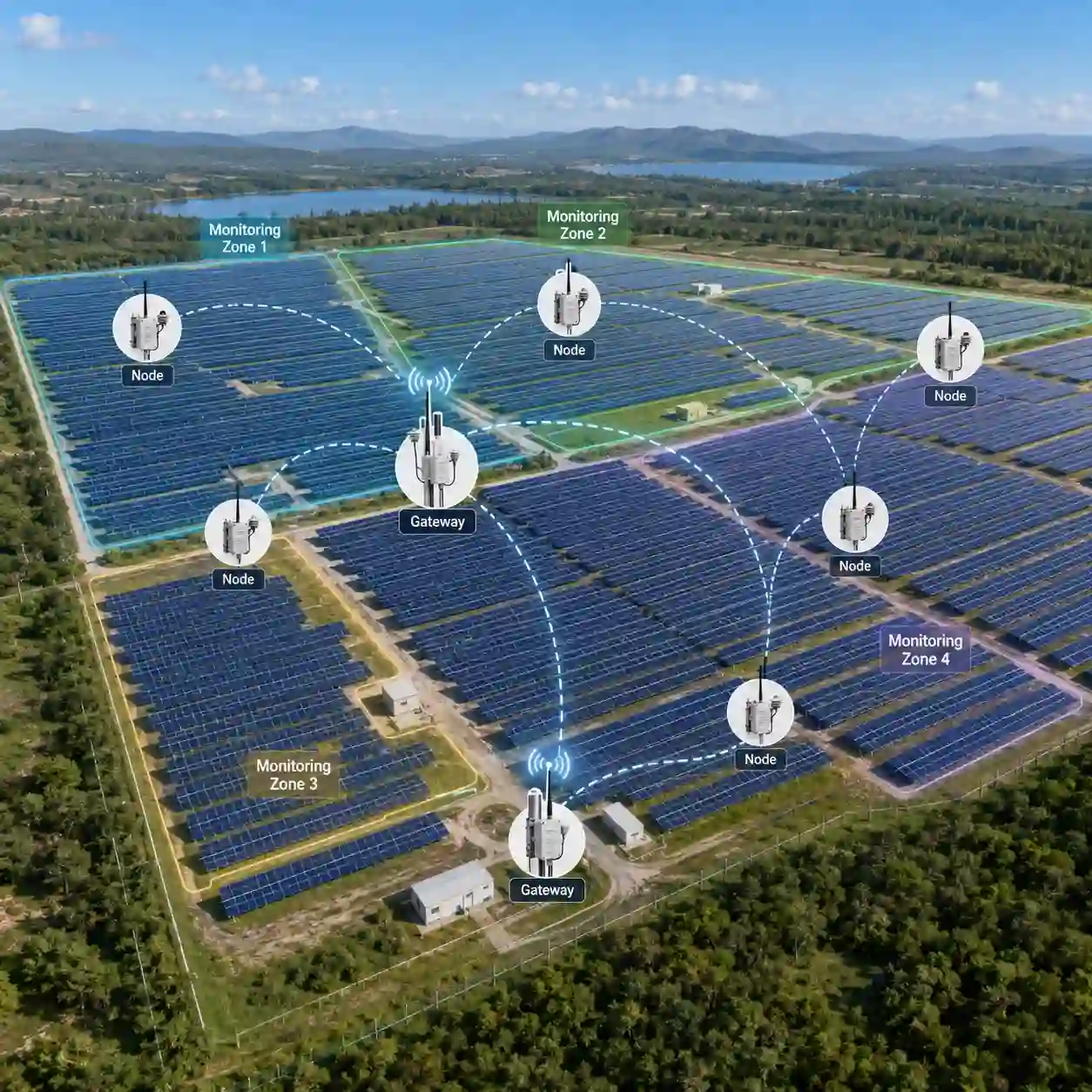
There is no universal rule stating that every PV block requires one monitoring node.
The correct deployment should be based on site conditions.
Step 1: Divide the solar farm into monitoring zones
Consider:
- inverter blocks
- topography
- module orientation
- tracker layout
- terrain
- dust exposure
- local weather differences
Step 2: Identify representative measurement points
Select locations where environmental measurements can represent meaningful operating zones.
Avoid installing nodes simply at equal distances without considering actual site conditions.
Step 3: Define the sensor package for each node
Not every node needs every sensor.
For example:
Performance Node
- POA irradiance
- module temperature
Weather Node
- wind
- air temperature
- humidity
Soiling Node
- soiling sensor
- irradiance
Step 4: Plan gateway locations
Gateway placement should consider:
- site dimensions
- terrain
- obstruction
- mounting height
- antenna location
- PV structures
- electrical rooms
- communication backhaul
Radio coverage should always be evaluated under the actual site conditions rather than relying solely on theoretical distance.
Step 5: Define reporting intervals
PV environmental sensors usually do not require continuous high-bandwidth transmission.
The appropriate reporting interval should depend on:
- performance-analysis requirements
- alarm requirements
- sensor type
- platform storage policy
- network capacity
- battery or power availability
Step 6: Integrate the monitoring platform
Before deployment, confirm:
- data protocol
- Modbus registers
- LoRaWAN payload format
- network-server configuration
- MQTT requirements
- API format
- timestamps
- device IDs
- alarm logic
This prevents integration problems later in the project.
Example Deployment: Large Utility-Scale Solar Farm
Consider a large PV plant divided into 20 monitoring zones.
A possible architecture might include:
- 1 main PV weather station
- 10 distributed irradiance monitoring nodes
- 10 PV module temperature monitoring points
- 4 wind monitoring nodes
- 2 rainfall monitoring points
- several LoRaWAN gateways
- 1 plant-level cloud or SCADA interface
The monitoring architecture could be:
PV Sensors
↓
RS485 LoRaWAN Nodes
↓
LoRaWAN Gateway Network
↓
4G / Ethernet Backhaul
↓
Central Server
↓
SCADA / EMS / O&M Platform
The exact number of nodes and gateways should always be determined according to plant layout and radio survey results rather than a fixed formula.
Benefits of LoRaWAN PV Monitoring Nodes
Reduced Communication Cabling
Wireless communication can significantly reduce the need for long signal cables between distributed monitoring points.
Easier Expansion
New monitoring nodes can be added as the solar farm expands or as additional measurements become necessary.
Better Spatial Data
Distributed measurements help identify localized variations that a single weather station may not detect.
Centralized Monitoring
Multiple environmental monitoring points can send data into one plant-level monitoring platform.
Flexible Sensor Integration
RS485 sensors can remain close to the measurement location while the LoRaWAN node handles long-distance wireless transmission.
Suitable for Remote PV Sites
LoRaWAN is specifically designed for low-power, wide-area IoT connectivity and can be deployed as private, public or hybrid networks depending on the application.
When Is LoRaWAN a Good Choice for Solar PV Monitoring?
LoRaWAN is particularly worth considering when:
- the solar farm covers a large area
- monitoring points are geographically distributed
- running communication cables is expensive
- sensors transmit relatively small amounts of data
- additional monitoring points may be added later
- a private wireless network is preferred
- a gateway can be installed with reliable backhaul
However, LoRaWAN should not automatically replace every wired connection.
For high-frequency data, tightly integrated control loops or locations with convenient existing cable infrastructure, wired communication may still be preferable.
The best PV monitoring architecture is often a hybrid system combining:
RS485 + LoRaWAN + 4G/Ethernet
How to Select a LoRaWAN PV Monitoring Node
Before selecting a node, project engineers should confirm the following requirements.
Sensor Interfaces
Check whether the node supports the required sensor outputs:
- RS485 Modbus
- analog
- pulse
- digital input
Number of Sensors
Determine how many sensors must connect to each node.
Power Supply
Possible options include:
- DC power
- solar power
- battery power
- hybrid power
LoRaWAN Frequency Band
The regional frequency plan must match the deployment country.
Environmental Protection
Outdoor PV monitoring devices should be selected according to the site’s:
- temperature range
- dust exposure
- rainfall
- humidity
- UV exposure
Platform Integration
Confirm support for the required:
- network server
- MQTT
- API
- private server
- cloud platform
JW-IoT LoRaWAN PV Monitoring Architecture
JW-IoT can configure distributed solar-farm monitoring systems combining:
- solar irradiance sensors
- Class A / Class B pyranometers
- PV module temperature sensors
- compact weather stations
- wind sensors
- rain gauges
- soiling monitoring systems
- RS485 data acquisition
- LoRaWAN wireless nodes
- LoRaWAN gateways
- 4G communication
- cloud monitoring
- API integration
For a complete plant-level design, visit:
Solar PV Monitoring System with IoT Automation
For the main meteorological monitoring station:
Solar Weather Monitoring Station for Utility Photovoltaic Power Plants
For distributed panel-temperature monitoring:
PV Module Temperature Sensors for Solar Plant Monitoring
For high-accuracy irradiance measurement:
Class A Pyranometer Solar Radiation Sensor
These pages form a logical monitoring chain from the sensor layer through plant-level solar monitoring.
Frequently Asked Questions
1. What is a LoRaWAN PV monitoring node?
A LoRaWAN PV monitoring node is a field IoT device that collects data from solar irradiance, module temperature or environmental sensors and transmits the measurements wirelessly to a LoRaWAN gateway.
The gateway then forwards the information to a cloud platform, SCADA system or energy management system.
2. Why use LoRaWAN in a large solar farm?
LoRaWAN can reduce the need for long communication cables between distributed monitoring locations.
It is especially useful when environmental monitoring points are spread across a large PV site and only small sensor datasets need to be transmitted periodically.
3. Can RS485 solar sensors connect to LoRaWAN?
Yes.
A common architecture is:
RS485 Sensor → LoRaWAN Node → Gateway → Cloud
The LoRaWAN node acts as the local interface between industrial sensors and the wireless communication network.
4. What sensors can be used with a LoRaWAN PV monitoring node?
Typical sensors include:
- solar irradiance sensors
- pyranometers
- PV module temperature sensors
- ambient temperature and humidity sensors
- wind sensors
- rain gauges
- soiling sensors
The exact combination depends on the purpose of each monitoring point.
5. Does LoRaWAN replace the PV weather station?
Usually not.
The main PV weather station normally provides reference meteorological data, while distributed LoRaWAN nodes provide additional localized measurements across the solar farm.
Using both can provide better spatial coverage.
6. How many LoRaWAN nodes does a solar farm need?
There is no fixed number.
The required quantity depends on:
- solar farm size
- terrain
- inverter-block layout
- module orientation
- environmental variability
- monitoring objectives
- communication coverage
A site-specific monitoring-point plan should therefore be prepared before deployment.
7. Can LoRaWAN PV data be integrated into SCADA?
Yes, provided the gateway, network server and application layer are configured for the required integration method.
Depending on the project, data may be transferred through MQTT, API or other supported protocols into a plant SCADA or O&M platform.
JW-IoT’s existing solar PV monitoring solution supports MQTT Cloud API and third-party platform integration.
Build a More Scalable PV Monitoring Network
Large solar farms need more than one environmental data point.
A properly designed distributed monitoring architecture can combine local RS485 sensors, LoRaWAN wireless nodes, LoRaWAN gateways and cloud or SCADA integration to create a scalable monitoring network across the entire plant.
JW-IoT can configure systems according to:
- PV plant capacity
- site dimensions
- number of monitoring zones
- required sensor parameters
- communication distance
- LoRaWAN frequency band
- gateway requirements
- cloud or SCADA integration requirements
Get LoRaWAN PV Monitoring Configuration
Send us:
1. Solar farm capacity
2. Approximate site dimensions
3. Number of PV blocks or monitoring zones
4. Required sensors
5. Project country
6. Existing SCADA/cloud platform
7. Required communication method
JW-IoT can then recommend a preliminary architecture including sensor nodes, gateways, communication methods and platform integration.