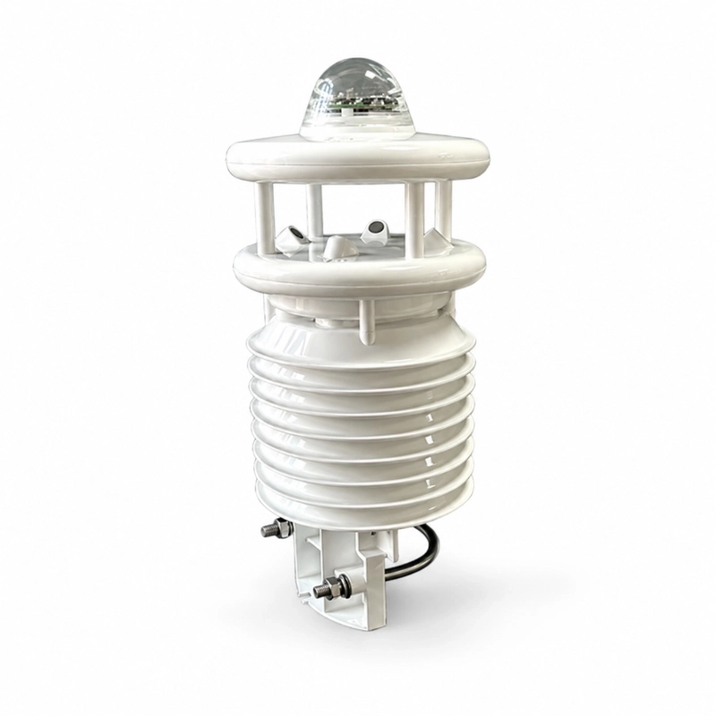
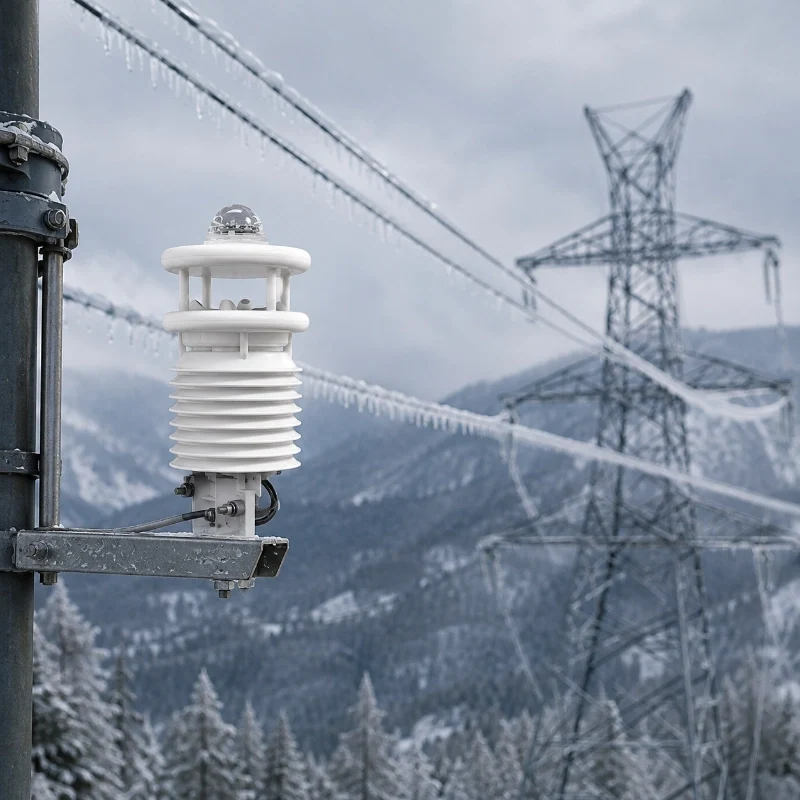
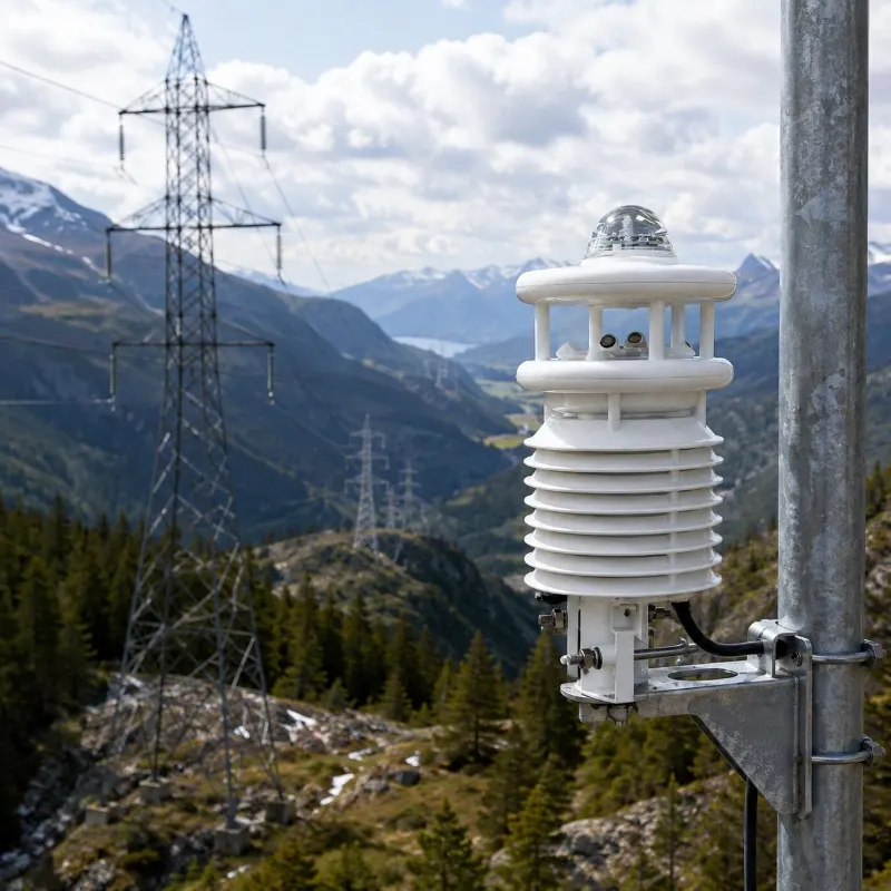
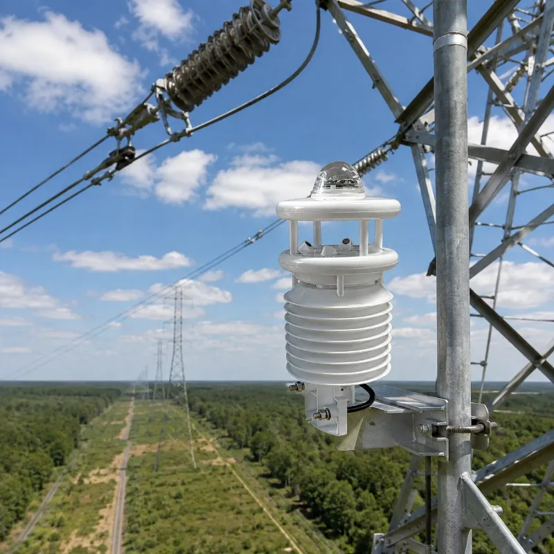
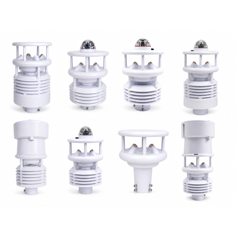
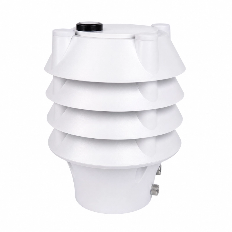
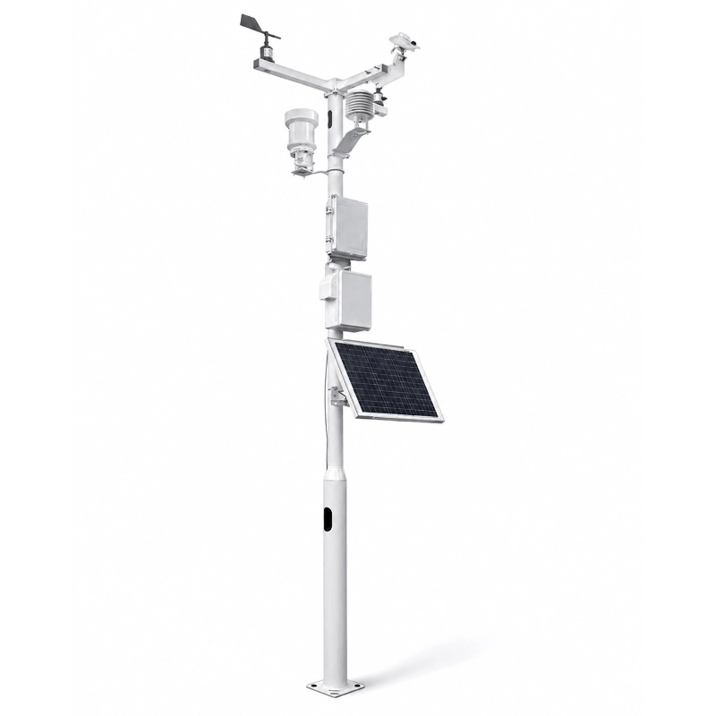
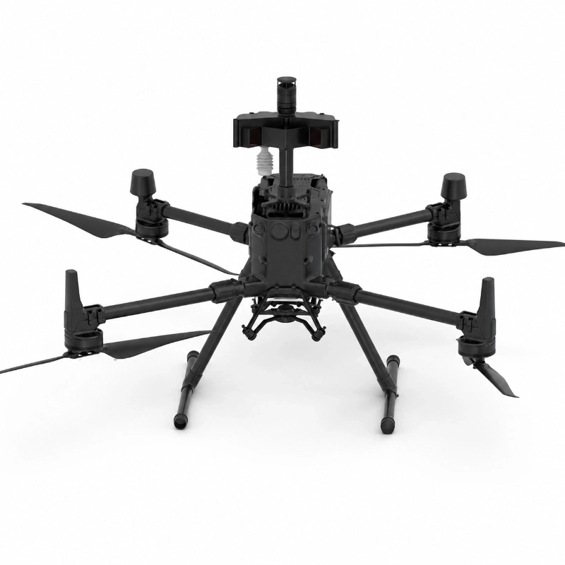
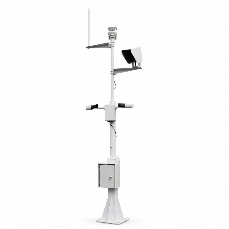
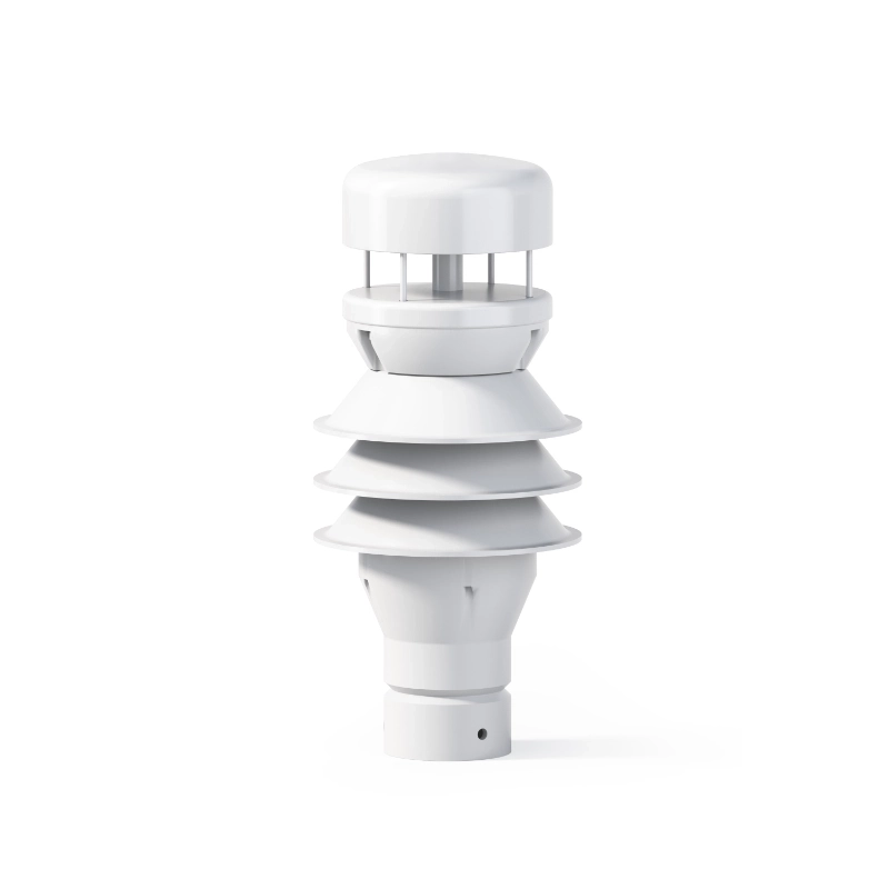
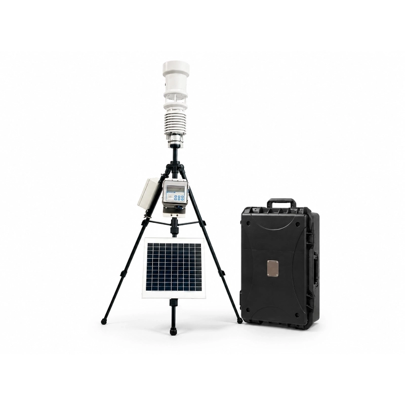
The JW-IWS-EG(LC34) Transmission Line Weather Monitoring System is an integrated microclimate, severe-weather recognition and remote early-warning solution developed for overhead transmission lines, power towers, substations and high-risk grid corridors.
The system continuously monitors local environmental conditions around transmission infrastructure, providing field data that regional weather forecasts may not accurately represent.
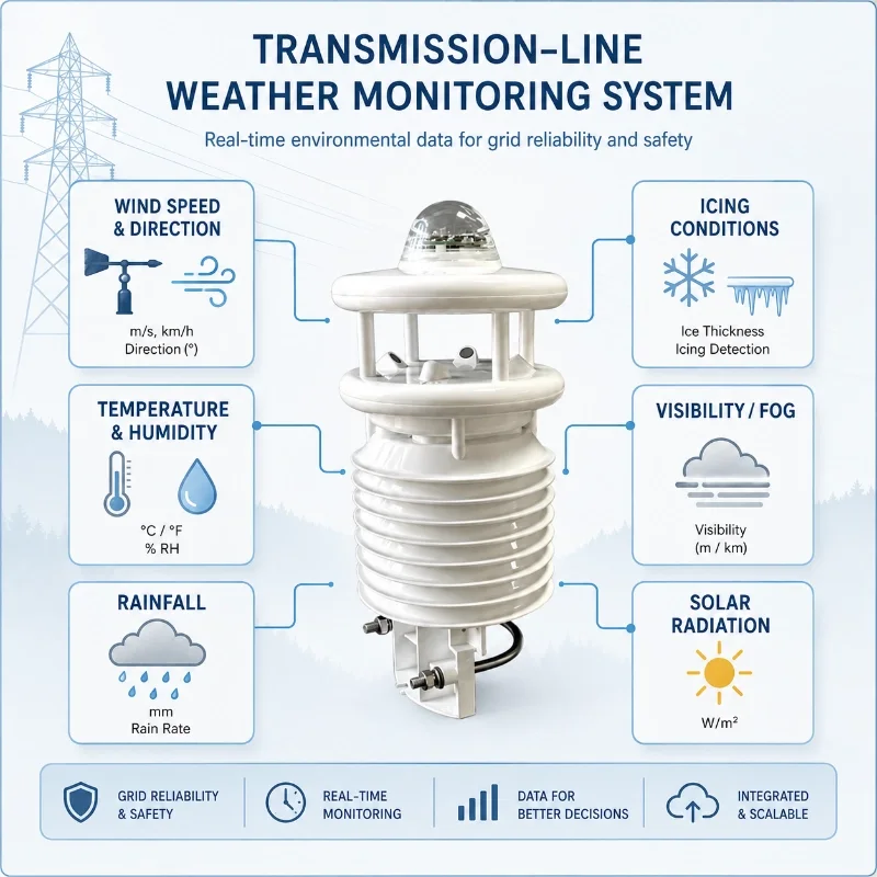
Depending on the project configuration, it can measure:
Air temperature
Relative humidity
Dew point
Wind speed
Wind direction
Atmospheric pressure
Rainfall
Solar radiation
Illuminance
UV radiation
Noise
PM1.0
PM2.5
PM10
Visibility
Local weather phenomena
The system can also support visual weather recognition for conditions such as sunshine, rain, snow, fog, haze, thunderstorm, hail, frost, dew and sandstorm.
With remote communication, cloud visualization and threshold alarms, it helps power utilities improve transmission-line inspection, strong-wind warning, icing-risk assessment, tower-foundation protection and preventive maintenance.
What Is a Transmission Line Weather Monitoring System?
A transmission line weather monitoring system is a field monitoring station installed near overhead conductors, transmission towers, tower foundations or critical sections of a power corridor.
Its purpose is to collect local meteorological and environmental data that may affect power-line safety.
Transmission lines often cross:
Mountains
Valleys
Rivers
Forests
Coastal areas
High-altitude regions
Icing-prone areas
Typhoon corridors
Landslide-prone slopes
Remote regions with limited access
Weather conditions in these locations may differ significantly from data collected by a distant public weather station.
Local monitoring therefore gives grid operators more representative information for operation, inspection and risk assessment.
Regional weather forecasts describe a wider area, but transmission-line risks are often highly localized.
A mountain saddle may experience stronger wind than a nearby town. A shaded high-altitude section may develop icing while lower line sections remain unaffected. Heavy rainfall may destabilize only one tower foundation or slope.
A field monitoring point can provide data directly from the affected corridor.
This supports:
More accurate strong-wind assessment
Faster identification of icing-prone conditions
Better inspection scheduling
Early detection of extreme weather
More targeted emergency response
Reduced unnecessary field visits
Historical comparison between weather and line events
Weather-Related Risks Monitored
Strong Wind and Conductor Galloping
Strong wind, crosswind and turbulent airflow may contribute to:
Conductor galloping
Wind-induced vibration
Wind deviation
Reduced electrical clearance
Tower and fitting stress
Damage to insulators or hardware
Increased risk at cross-valley and cross-river sections
Wind speed alone does not fully determine conductor behaviour, but continuous wind data provides important context for line-risk assessment.
Recommended parameters include:
Wind speed
Wind direction
Gust conditions
Air temperature
Precipitation
Video observation
Optional tower tilt or vibration
Icing and Freezing Conditions
Conductor icing can increase mechanical load and affect line safety.
Weather conditions associated with icing may include:
Low temperature
High humidity
Freezing rain
Fog
Supercooled water droplets
Low wind or changing wind
Frost and dew-point conditions
The system can provide the meteorological inputs required for icing-tendency analysis.
For projects requiring direct icing thickness or conductor-load measurement, additional dedicated sensors may be required.
Heavy Rainfall and Tower-Foundation Risk
Long-duration or intense rainfall can affect:
Tower-foundation erosion
Slope stability
Surface runoff
Landslide risk
Flash-flood risk
Access-road conditions
Drainage around tower bases
Rainfall monitoring can be combined with:
Soil moisture
Groundwater level
Slope displacement
Tilt
Crack monitoring
Cameras
Water-level sensors
Fog, Haze and Low Visibility
Fog, haze, snow and heavy rainfall can reduce visibility and affect:
Manual inspection
Drone inspection
Helicopter inspection
Emergency access
Camera image quality
Maintenance safety
Optional visibility monitoring and image recognition provide additional information for field operations.
High Temperature and Fire Risk
High temperature, low humidity and strong wind may increase vegetation and wildfire risk along some transmission corridors.
The system may be expanded with:
Smoke detection
Fire-weather parameters
Video monitoring
Thermal imaging
Soil moisture
Vegetation monitoring
Local alarm devices
Coastal and Salt-Fog Environments
Coastal transmission lines may face:
Strong wind
Typhoons
High humidity
Salt spray
Corrosion
Sudden rainfall
Electrical-insulation contamination
Equipment materials, connectors, mounting structures and communication enclosures should be selected for the local corrosion environment.
Parameters Monitored
Air Temperature
Temperature data supports:
Icing-risk analysis
Thermal operating assessment
Frost and freezing warning
Sensor compensation
Environmental trend monitoring
Relative Humidity and Dew Point
Humidity and dew point help assess:
Condensation
Frost
Fog formation
Icing tendency
Insulator surface conditions
Local atmospheric moisture
Wind Speed and Wind Direction
Wind data is critical for evaluating:
Crosswind conditions
Gust events
Corridor airflow
Conductor galloping risk
Wind deviation
Tower exposure
Typhoon impact
A high-precision ultrasonic wind sensor can be selected for projects requiring no moving parts and reduced maintenance.
Noise monitoring may support selected projects involving:
Corona-related environmental studies
Nearby construction activity
Industrial-zone monitoring
General environmental networks
It should not be treated as a direct substitute for specialized electrical-discharge diagnostic equipment.
Recognizable Weather Conditions
Depending on the camera, recognition algorithm and selected configuration, the system can support identification of:
Sunny conditions
Rain
Snow
Fog
Haze
Thunderstorm conditions
Hail
Frost
Dew
Sandstorm
Cloud cover
Reduced visibility
Image recognition should be used together with measured sensor data rather than as the only source for critical alarms.
System Architecture
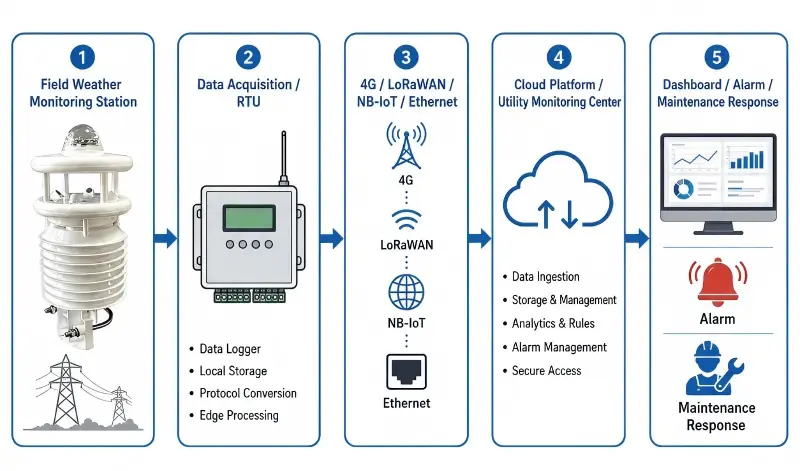
A typical transmission-line monitoring architecture is:
Microclimate Sensors and Camera
→ Data Acquisition Terminal
→ 4G / LoRaWAN / NB-IoT / Ethernet
→ Cloud Server or Utility Platform
→ Dashboard, Alarm and Maintenance Response
Field Layer
Sensors are installed at:
Transmission towers
Tower foundations
Line corridors
Mountain saddles
Cross-river sections
Icing-prone line segments
Landslide-prone slopes
Coastal towers
Remote substations
Key inspection points
Data-Acquisition Layer
The field terminal can collect data through:
RS485 Modbus RTU
Analogue signals
Pulse inputs
Digital inputs
Camera interfaces
Additional sensor expansion ports
Communication Layer
Available communication methods may include:
4G LTE
LoRaWAN
NB-IoT
Ethernet
Private utility communication network
Satellite communication for selected remote projects
Cloud and Platform Layer
The platform can provide:
Real-time data display
Multi-site map view
Historical trend curves
Device status monitoring
Alarm-threshold settings
Weather-image display
Weather-event recognition
Data export
Reporting
SMS, email or app notification
API integration
Integration with existing utility O&M systems
Communication Selection
4G LTE
Suitable when:
Towers have cellular coverage;
Each site can connect directly to the cloud;
Image or higher-volume data is transmitted;
Deployment points are widely separated.
LoRaWAN
Suitable when:
Multiple monitoring points are located in one corridor;
A gateway can cover several towers;
Sensor data volume is relatively low;
Power consumption must be reduced.
Ethernet
Suitable for:
Substations
Fixed facilities
Sites with existing wired communication
Local control centres
Typical Applications
Mountain Transmission Lines
Mountain corridors may experience:
Strong localized wind
Rapid temperature changes
Fog and icing
Landslides
Limited communication
Difficult manual access
Monitoring points should be placed at representative high-risk locations rather than uniformly without risk assessment.
Cross-Valley and Cross-River Lines
These sections may face:
Strong crosswind
Turbulence
Conductor galloping
Greater spans
Wind-direction changes
Difficult inspection access
High-quality wind measurements are especially important.
High-Altitude and Icing-Prone Lines
Recommended monitoring may include:
Temperature
Humidity
Dew point
Wind
Rainfall or freezing precipitation
Camera
Visibility
Dedicated icing sensor
Solar-powered communication terminal
Coastal Transmission Corridors
Coastal projects should consider:
Typhoon wind
Salt spray
Corrosion
High humidity
Heavy rainfall
Waterproof and corrosion-resistant enclosures
Reinforced mounting structures
Desert and Sandstorm Areas
Recommended parameters may include:
Wind speed
Wind direction
PM10
Visibility
Temperature
Solar radiation
Sandstorm recognition
Enclosure dust protection
Tower-Foundation and Slope Monitoring
Weather stations can be combined with:
Draw-wire displacement sensors
Tilt sensors
Crack sensors
Soil-moisture sensors
Groundwater sensors
Rain gauges
GNSS devices
Cameras
This creates a more complete tower-foundation and geological-risk monitoring system.
Installation Recommendations
Select High-Risk and Representative Locations
Prioritize:
High-wind passages
Mountain saddles
Icing-prone elevations
Cross-river spans
Coastal towers
Landslide-prone slopes
Heavy-rainfall zones
Remote sections with long inspection intervals
Avoid Tower-Wake Interference
Tower members, conductors and nearby structures may disturb airflow.
The wind sensor should be installed where tower-induced turbulence is minimized and where the measured direction represents the target airflow.
Keep the Rain Gauge Level
A rain gauge should be installed horizontally and away from severe splash, obstruction and structure-induced wind effects.
Protect Temperature and Humidity Measurement
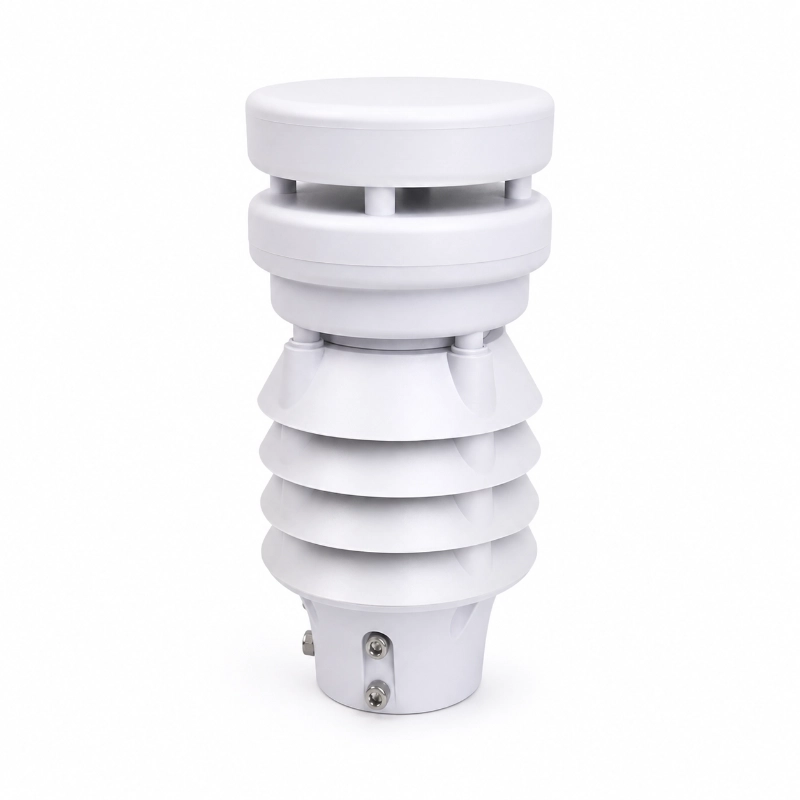
Install the temperature and humidity sensor inside an appropriate radiation shield.
Avoid:
Direct solar heating
Enclosure heat
Exhaust outlets
Solar-controller heat
Battery heat
Large metal surfaces that become hot
Position the Camera Carefully
Avoid:
Direct sunrise or sunset glare
Tower members blocking the field of view
Strong night reflections
Water accumulation on the lens
Unrepresentative viewing direction
Protect Cables and Connectors
Use:
UV-resistant cable
Waterproof connectors
Shielded communication cable
Cable conduit
Drip loops
Surge protection
Grounding
Lightning protection
Mechanical cable protection
Evaluate Solar-Power Capacity
Solar-power design should consider:
Total equipment consumption
Camera operation
Transmission frequency
Winter solar radiation
Battery temperature
Consecutive cloudy days
Heating requirements
Battery ageing
Panel shading from towers and conductors
Alarm and Early-Warning Strategy
Alarm thresholds should be set according to:
Line voltage class
Conductor type
Span length
Tower design
Local climate
Historical faults
Terrain
Icing history
Utility maintenance procedures
Emergency-response plans
Possible alarms include:
High wind speed
Abnormal wind direction
Low temperature and high humidity
Freezing-rain conditions
Heavy rainfall
Cumulative rainfall
Low visibility
Severe weather recognition
Communication interruption
Low battery voltage
Sensor fault
Camera offline
Door or enclosure alarm
A single weather reading should not automatically determine a critical line-failure condition. Multi-parameter confirmation and engineering rules are recommended.
1. What is a transmission line weather monitoring system?
A
A transmission line weather monitoring system is a microclimate monitoring solution installed near power lines or transmission towers to measure local weather and environmental conditions in real time.
Q
2. What parameters can this system monitor?
A
It can monitor ambient temperature, humidity, dew point, wind speed, wind direction, rainfall, solar radiation, illuminance, UV radiation, noise, PM1.0, PM2.5, PM10, and weather conditions.
Q
3. Can JW-IoT customize the monitoring parameters?
A
Yes. Its tripod structure, solar power design, and portable configuration make it suitable for temporary sites, field work, and mobile monitoring tasks.
Q
4. Why is local microclimate monitoring important for transmission lines?
A
Local monitoring provides more accurate weather data around the line corridor, helping utilities identify icing, strong wind, heavy rainfall, fog, and other conditions that may affect line safety.
Q
5. Can JW-IoT support weather recognition functions?
A
Yes. JW-IoT can support weather phenomenon recognition for multiple climate conditions such as rain, snow, fog, haze, hail, and sandstorm, depending on system configuration.
Q
6. Is this system suitable for harsh outdoor environments?
A
Yes. It is designed for long-term outdoor deployment and is suitable for mountains, plains, coastal environments, and remote transmission corridors.
Q
7. Can the system be used for icing and disaster prevention?
A
Yes. It can help identify environmental conditions that may lead to icing, thunderstorm risk, sandstorm events, or other hazards affecting transmission line safety.
Q
8. Does JW-IoT provide remote monitoring integration?
A
Yes. JW-IoT can support integration with cloud platforms, remote monitoring centers, and utility management systems for real time data viewing and alarm handling.
Q
9. What industries or users typically use this system?
A
Typical users include power utilities, grid operators, transmission maintenance teams, smart grid integrators, and infrastructure monitoring providers.
Q
10. Can the system trigger alarms?
A
Yes. The system can support threshold-based warning and alarm functions to help operators respond quickly to abnormal weather conditions.
Q
11. Does JW IoT support OEM and project customization?
A
Yes. JW-IoT can support OEM, ODM, parameter customization, and project-based integration for different transmission line monitoring applications.
Q
12. Why choose JW-IoT for transmission line weather monitoring?
A
JW-IoT provides flexible monitoring solutions, customizable sensing options, data platform integration, and practical experience in environmental and infrastructure monitoring applications.
 +86 13520127780
  info@jingelway.com