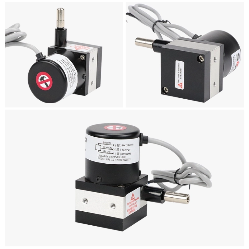
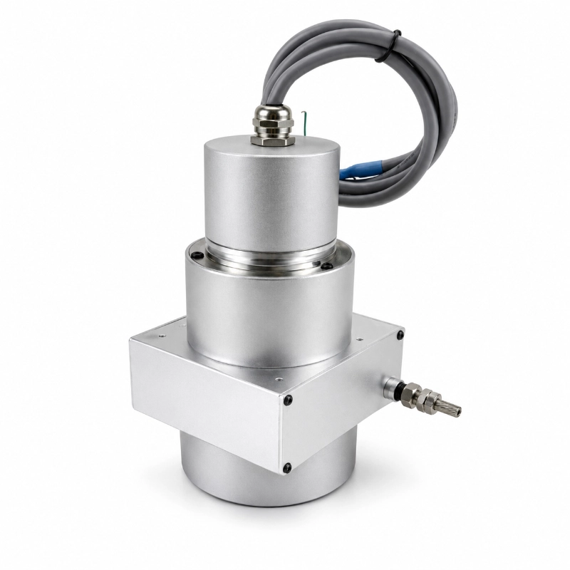
ال مستشعر إزاحة سلك السحب JW-WPS-XS(S10) is a compact linear position measuring device designed for displacement monitoring over a 0–1000mm measuring range.
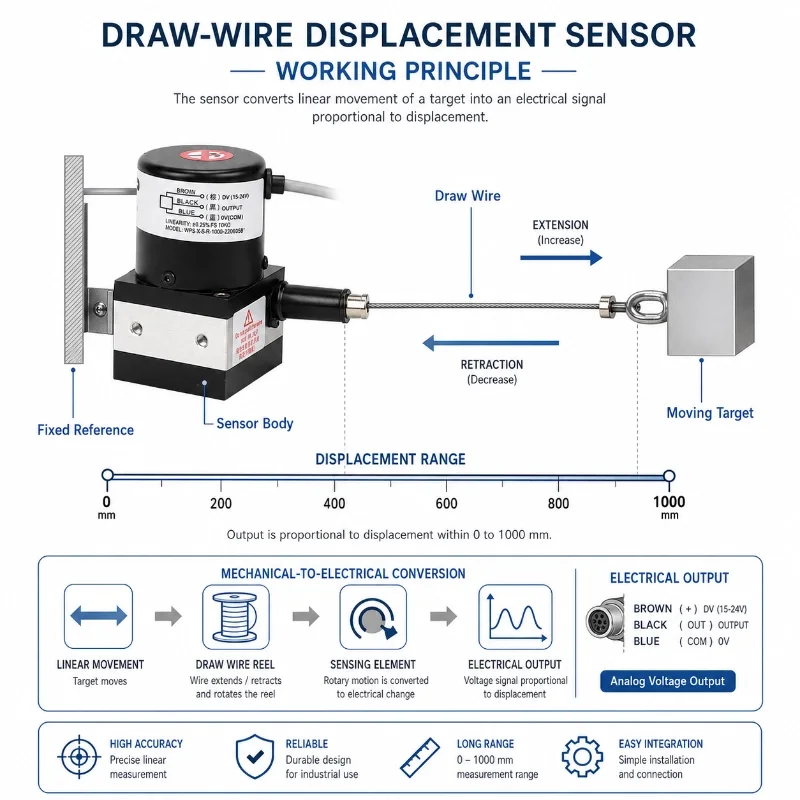
Using a retractable measuring cable and an internal sensing mechanism, the sensor converts linear cable extension into an electrical signal corresponding to the position of a moving object.
Its compact XS-series housing makes it suitable for industrial equipment where installation space is limited but a measuring stroke of up to one metre is required.
Available output configurations include resistance, voltage, current, incremental pulse, and selected digital interfaces, allowing integration with compatible PLCs, industrial controllers, and data acquisition systems.
Typical applications include industrial machinery position feedback, lifting equipment, telescopic mechanisms, hydraulic gate positioning, and relative displacement measurement.
1. How Does a Draw Wire Displacement Sensor Work?
A مستشعر إزاحة سلك السحب, also called a cable extension sensor or string potentiometer in potentiometric configurations, measures linear movement through the extension and retraction of a measuring cable.
The sensor housing is installed on a fixed reference point, while the free end of the measuring cable is attached to the moving component.
As the target moves away from the sensor:
The measuring cable extends.
تدور البكرة الداخلية.
يقوم عنصر الاستشعار بتحويل حركة البكرة إلى خرج كهربائي.
A compatible controller or data acquisition device interprets the signal as linear position.
When the target moves back, the internal return mechanism retracts the cable and the output changes accordingly.
This arrangement provides a compact alternative to rigid, long-body linear displacement sensors where a longer measurement stroke is needed.
Key measurement principle: The sensor measures relative linear movement between its mounting point and the cable endpoint. It does not independently determine the absolute geographic position of the monitored object.
ing and conversion formula should follow the actual product datasheet supplied with the ordered model.
2. المواصفات الفنية
المعلمة
مواصفة
نموذج المنتج
JW-WPS-XS(S10)
نوع المستشعر
Draw Wire / Cable Extension Displacement Sensor
مسلسل
WPS-XS
نطاق القياس
0–1000 مم
الخطية القياسية
0.25%FS
الخطية الدقيقة
0.05%–0.08%FS
قابلية التكرار
0.01%FS–0.005%FS
الخرج الحالي
4–20mA / 20–4mA
خرج الجهد
0–10V DC / 10–0V DC
مقاومة الخرج
0–5kΩ / 0–10kΩ
Incremental Pulse Output
3600–5000 PPR, A/B or A/B/Z phase options
واجهة رقمية
RS485, selected encoder configurations
جهد التغذية
24V DC for applicable powered versions
Pulse Version Supply
5–24V DC
تصنيف الحماية
IP65
مواد البناء
سبائك الألومنيوم
Specified Service Life
5 Million Reciprocating Cycles
طريقة التركيب
Bracket or Threaded Mounting
Fixing Screws
M4
Bracket Hole Spacing
28 ±0.5 مم
Recommended Bracket Separation
40–55mm
Cable-End Thread
M6
Configuration note: Output type, power supply, linearity, and electrical connections vary by version. RS485 availability does not automatically confirm Modbus RTU compatibility. The required protocol and pin assignments should be confirmed before ordering.
3. Electrical Output Options
The JW-WPS-XS series offers multiple output configurations to accommodate different industrial measurement systems.
3.1 Resistance Output
Available resistance options include 0–5kΩ and 0–10kΩ.
A resistance output can be used with compatible signal-conditioning equipment or controllers designed for potentiometric position measurement.
The actual resistance-to-displacement relationship must be taken from the ordered sensor specifications.
3.2 Analog Current Output
Available current signal options include:
4-20 مللي أمبير
20–4mA
A 4–20mA draw wire displacement sensor is useful when connecting position measurements to industrial analog input modules and compatible data acquisition equipment.
The current output must be matched to the required supply voltage, input load, and signal scaling.
3.3 Voltage Output
Available voltage output options include:
0-10 فولت تيار مستمر
10–0V DC
These configurations can interface with suitable PLC or controller voltage inputs.
3.4 Incremental Encoder and Digital Output
The product documentation also lists incremental pulse configurations with A/B or A/B/Z phases and pulse resolution options of approximately 3600–5000 PPR.
RS485 and other encoder-related output possibilities are identified in the product series information.
Digital output protocol, encoder resolution, and electrical requirements must be verified for the selected version.
مهم: Analog, resistance, pulse, and digital outputs represent different product configurations and should not be assumed to operate simultaneously.
4. التطبيقات الصناعية
4.1 Machinery Position Feedback
Industrial machines frequently require position feedback for moving platforms, mechanical slides, and extendable components.
The compact draw wire sensor can measure the displacement between a fixed machine frame and a moving part.
تشمل التطبيقات المحتملة ما يلي:
Sliding platform travel
Telescopic mechanism extension
Machine stroke measurement
معدات مناولة المواد
Production equipment position feedback
Its compact housing can be particularly useful when the machine cannot accommodate a rigid position sensor as long as the measurement stroke.
4.2 Lifting and Height Measurement
Draw wire position sensors can monitor the movement of lifting platforms and mechanical lifting assemblies.
The measuring cable follows the movement of the target, while the output provides a position-related signal for a compatible monitoring or control system.
Actual suitability depends on the required travel speed, cable loading, cycle frequency, and installation geometry.
The sensor should not be used as a safety-rated lifting protection device without the necessary system-level assessment.
4.3 Hydraulic Gate and Door Position Monitoring
For suitable mechanical gate and door arrangements, the cable extension sensor can measure the movement of the gate or actuator.
قد تشمل التطبيقات النموذجية ما يلي:
Sluice gate opening position
Industrial sliding door travel
Mechanical actuator stroke
Gate position feedback to a PLC
Local or remote position monitoring
For outdoor water infrastructure, the cable route, mounting hardware, environmental exposure, and enclosure sealing must be carefully evaluated.
4.4 Hydraulic and Telescopic Equipment
Hydraulic machinery may use draw wire sensors to measure external cylinder movement or the displacement of connected mechanisms.
The sensor provides an alternative to direct rod-mounted measurement when a cable connection is mechanically suitable.
However, alignment, travel speed, cable retraction force, and environmental conditions must be considered during selection.
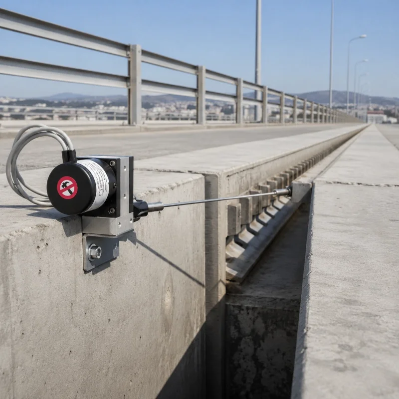
4.5 Structural Relative Displacement Monitoring
A draw wire displacement sensor can also be used to measure relative movement between two suitable reference points.
تشمل التطبيقات المحتملة ما يلي:
حركة وصلة التمدد
Structural gap changes
Selected retaining-wall displacement points
Movable structural components
Local deformation measurement
For structural monitoring projects, the installation geometry and reference-point stability must be evaluated by the project engineer.
Both draw wire and rod-type linear displacement sensors are used for position feedback, but their mechanical structures differ.
ميزة
مستشعر سلك السحب
مستشعر خطي من نوع القضيب
Measuring Mechanism
كابل قابل للسحب
Moving Rod or Slider
Housing Length
Compact Relative to Stroke
Often Related to Stroke
Target Connection
نقطة نهاية الكابل
Mechanical Rod/Slider
Alignment Requirement
Cable Travel Direction
Rod or Slider Axis
Exposed Moving Parts
Measuring Cable
قضيب أو منزلق
Installation Selection
Suitable for Remote Moving Points
Suitable for Direct Linear Motion
A draw wire sensor is generally preferable when the measuring stroke is relatively long compared with the available housing space.
A rod-type sensor may be preferable where the moving assembly allows direct mechanical coupling and the measuring stroke is compatible with the sensor body.
Proper mechanical installation is important for reliable displacement measurement and cable service life.
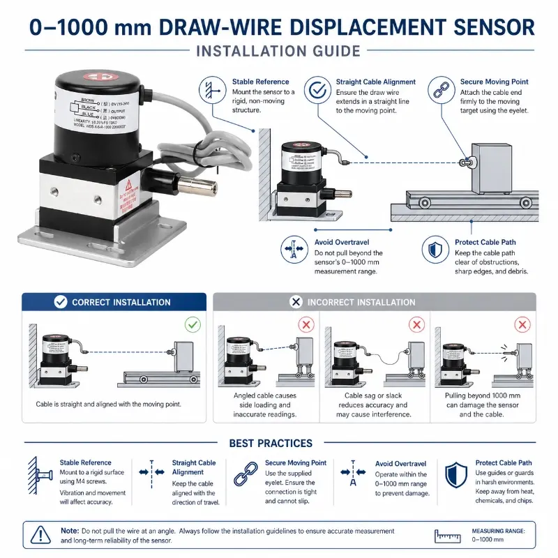
6.1 تثبيت غلاف المستشعر
Mount the sensor body to a stable bracket or machine frame using the appropriate mounting holes and fasteners.
The existing product specifications list M4 mounting screws and a bracket hole spacing of 28 ±0.5mm.
6.2 Align the Measuring Cable
The measuring cable should extend and retract along its intended travel direction.
Avoid excessive side loading, which can increase friction and cause cable or outlet wear.
6.3 Protect the Cable Path
Keep the cable away from sharp edges, moving machine parts, abrasive surfaces, and obstacles.
Do not allow the cable to bend around unapproved guides or contact structures during operation.
6.4 Avoid Sudden Cable Retraction
Control the cable during installation.
Do not release an extended cable suddenly, as uncontrolled retraction may damage the measuring mechanism.
6.5 Reserve Measuring Travel
Account for the initial cable extension and maximum expected movement when selecting the measuring range.
Do not repeatedly operate the device at the mechanical end of its travel.
6.6 Check Electrical Compatibility
Before connecting the sensor to a PLC or data logger, confirm:
Required supply voltage
Output signal type
تعريف الأسلاك
Input range and scaling
Grounding and shielding
Connector configuration
7. PLC and Remote Monitoring Integration
The JW-WPS-XS sensor can be incorporated into an industrial monitoring system using a suitable output version and compatible data acquisition equipment.
A typical arrangement is:
Draw Wire Sensor → PLC / Data Logger / RTU → Monitoring or Control System
For projects requiring remote telemetry, an appropriately configured acquisition device may transfer measurements through Ethernet, cellular, or other supported communication networks.
Possible system-level functions include displacement trend recording, movement-rate analysis, and threshold-based notifications.
These capabilities are provided by the external acquisition and monitoring system rather than by the mechanical sensor alone.
The measuring range should accommodate both the initial cable extension and the complete expected target movement.
For example, a 1000mm sensor may be appropriate for an application with approximately 700mm of expected travel, provided sufficient range remains for mounting offset, unexpected movement, and any required margin.
قبل الاختيار، ضع في اعتبارك ما يلي:
Maximum expected displacement
Installation starting position
Expected movement direction
Mechanical travel limits
Cable speed and acceleration
Cycle frequency
Operating environment
دقة القياس المطلوبة
If the application requires more than 1000mm of travel, or the available measuring margin is insufficient, consider the 0–2500mm Draw Wire Displacement Sensor.
9. Maintenance Recommendations
Periodic inspection helps maintain measurement consistency and reduce mechanical failures.
تشمل الفحوصات الموصى بها ما يلي:
Measuring cable condition
Cable outlet wear
Smooth cable extension and retraction
Mounting screw tightness
Endpoint connection stability
Signal cable and connector condition
Housing seals
Unexpected output changes
Ensure the cable path remains clear throughout the complete operating stroke.
Do not apply lubricant or modify the spring mechanism unless permitted by the supplied maintenance documentation.
10. Request a Quotation
Looking for a compact مستشعر إزاحة سلك السحب for industrial positioning, machinery travel measurement, or equipment integration?
JW-IoT can assist with selecting the appropriate measuring range and output configuration.
يرجى تقديم ما يلي:
Required measurement stroke
إشارة الخرج
جهد التغذية
بيئة التركيب
Mounting requirements
Expected movement speed
Purchase quantity
تواصل مع JW-IoT to request product specifications and a quotation.
التعليمات
Q
1. What is the measuring range of the JW-WPS-XS draw wire sensor?
A
The JW-WPS-XS(S10) is designed for displacement measurement from 0 to 1000mm, with range selection depending on the application.
Q
2. What is the difference between a draw wire sensor and a string potentiometer?
A
A draw wire sensor describes the retractable cable measurement mechanism. A string potentiometer is a draw wire sensor that uses a potentiometric sensing element. Other draw wire configurations may use encoder or electronic output technologies.
Q
3. Does this sensor support 4–20mA output?
A
Yes. A 4–20mA output configuration is listed in the product specifications, subject to the selected version.
Q
4. Is the draw wire sensor suitable for outdoor installation?
A
The product is specified with an IP65 enclosure rating. Outdoor suitability also depends on cable exposure, mounting, humidity, temperature, and other site conditions.
Q
5. Can the sensor connect to a PLC?
A
Yes. Compatible output configurations can connect to PLC analog or digital input equipment. Electrical requirements must match the selected sensor version.
Q
6. Does the RS485 output support Modbus RTU?
A
The current product information lists RS485 but does not clearly confirm the communication protocol. Request the communication documentation before integration.
Q
7. How accurate is the 0–1000mm sensor?
A
The product documentation lists standard linearity of 0.25%FS and precision options of 0.05%–0.08%FS. These are linearity specifications rather than guarantees of total measurement uncertainty.
Q
8. How do I choose between the 1000mm and 2500mm draw wire sensors?
A
Choose the 1000mm XS-series model when the required displacement and installation allowance fit within its available travel. Consider the 2500mm WPS-S model when greater measurement stroke is required.
 +86 13520127780
 info@jingelway.com