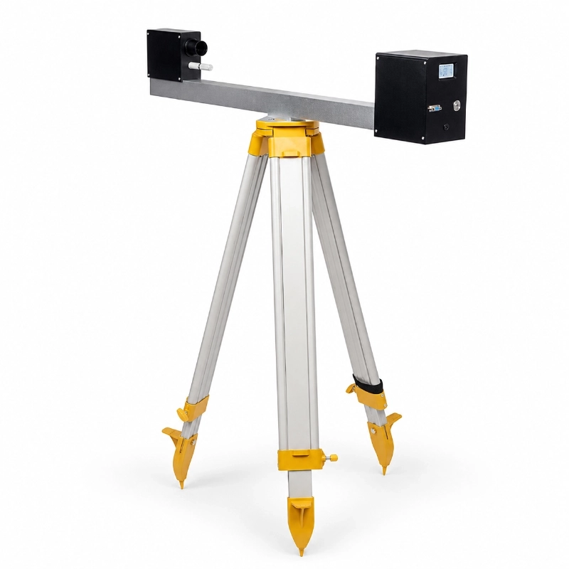
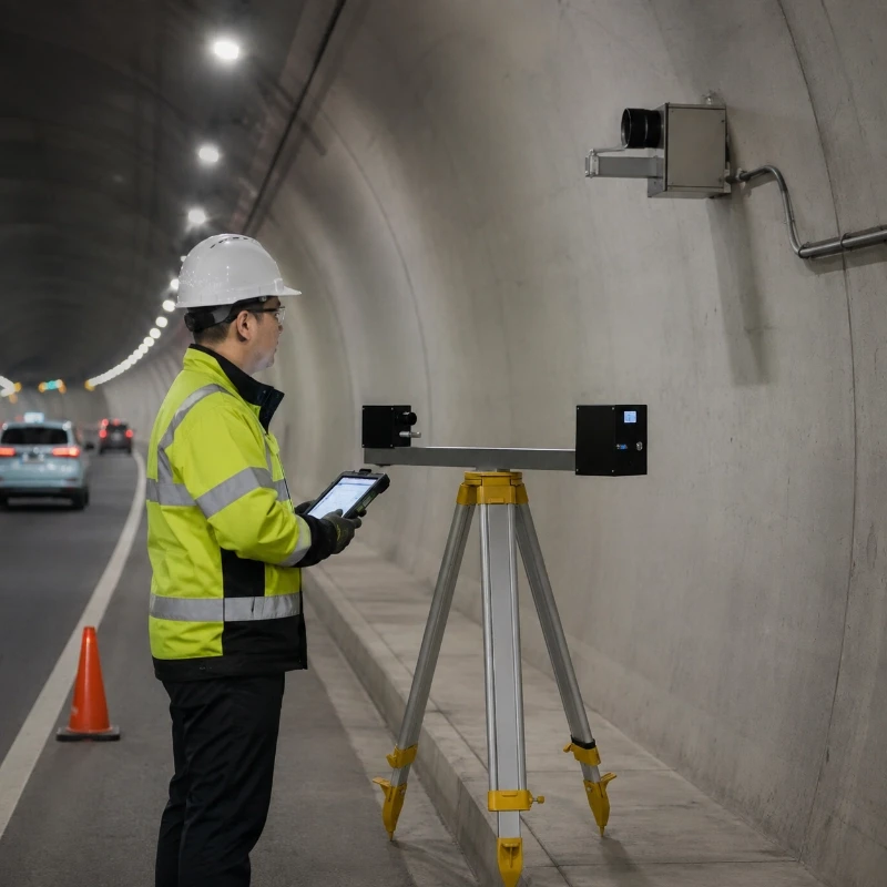
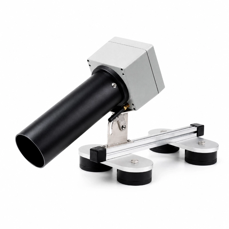
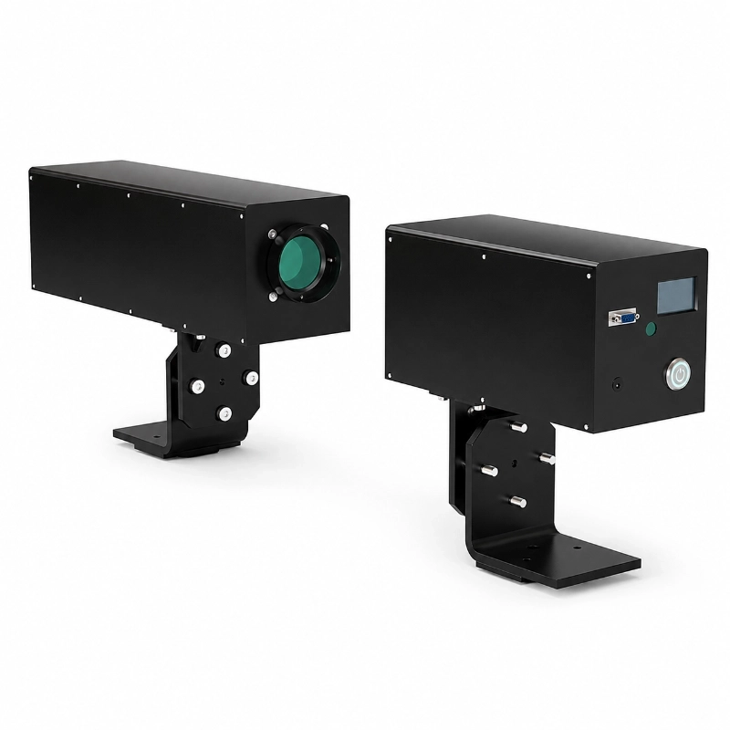
The JW-TRA10(HY04) Portable Transmittance Meter is a field inspection instrument designed for rapid measurement of atmospheric light transmittance and visibility-related conditions in tunnels, underground roads and enclosed traffic environments.
The portable design allows maintenance teams, tunnel operators, engineering contractors and testing personnel to conduct temporary measurements at different locations without installing a permanent monitoring station.
Typical uses include:
Tunnel visibility inspection
Atmospheric transmittance measurement
Smoke and haze condition assessment
Ventilation-performance checks
Fixed visibility-sensor verification
New tunnel acceptance testing
Maintenance inspections
Before-and-after cleaning comparison
Temporary monitoring after construction or incidents
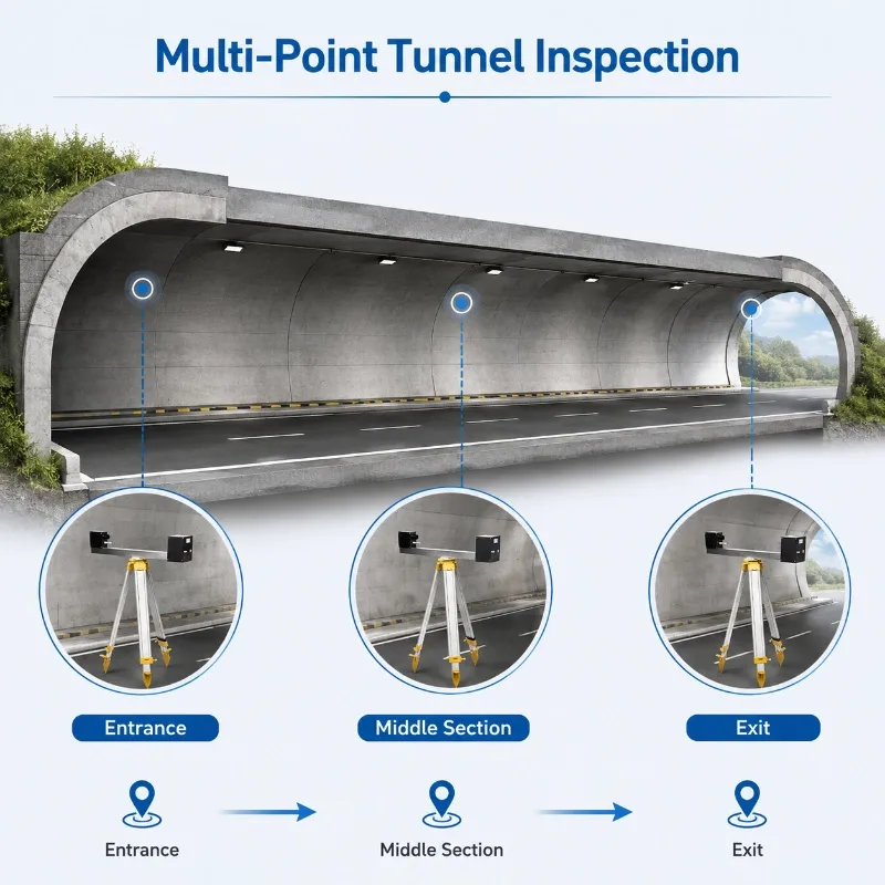
Multi-point field surveys
The instrument is particularly suitable when users need to move between several tunnel sections and obtain rapid on-site readings.
What Is a Portable Transmittance Meter?
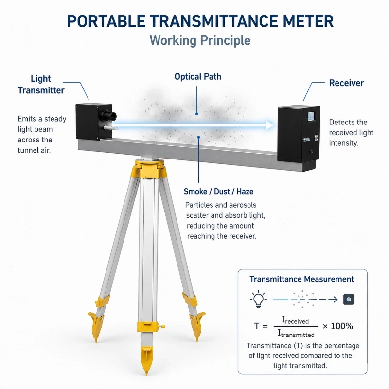
A portable transmittance meter measures how much light passes through a defined air path between an optical transmitter and receiver.
When the air is clean, more of the transmitted light reaches the receiver.
When smoke, dust, water mist, exhaust particles or other aerosols are present, part of the light is absorbed or scattered. The amount of light received decreases, resulting in a lower transmittance value.
In practical tunnel monitoring:
Higher transmittance generally indicates clearer air;
Lower transmittance generally indicates greater optical attenuation;
The result must be interpreted together with the test path length and measurement conditions.
The JW-TRA10(HY04) is positioned as a portable field instrument for convenient and rapid on-site detection.
What Does Atmospheric Transmittance Mean?
Atmospheric transmittance is the ratio between the light received after passing through the monitored air path and the light emitted by the source under the defined test condition.
It can be expressed conceptually as:
Transmittance =
Received Light Intensity ÷ Emitted Light Intensity
A value closer to 100% indicates that a larger proportion of the emitted light reached the receiver.
A lower value means that more light was attenuated by:
Smoke
Dust
Vehicle exhaust
Fog
Water mist
Aerosols
Airborne particles
Optical-window contamination
Temporary obstruction
The measured value should not be compared across different tests unless the optical path, instrument configuration and test procedure are consistent.
Transmittance, Extinction and Visibility
These three terms are related but are not identical.
Transmittance
Transmittance describes the proportion of light that passes through a defined optical path.
Optical Extinction
Optical extinction describes the reduction of light caused by absorption and scattering.
A higher extinction condition normally produces lower transmittance over the same path.
Visibility
Visibility describes how far an object can be seen and recognized under defined contrast conditions.
Some tunnel systems convert optical attenuation or transmittance data into visibility-related indicators. The calculation method depends on the instrument, optical path and adopted standard.
For this reason, the page should not state that a specific transmittance value always equals one universal visibility distance unless the conversion method is confirmed in the product datasheet.
Why Measure Visibility and Transmittance in Tunnels?
Visibility inside a road tunnel can be affected by vehicle exhaust, suspended particles, smoke, ventilation conditions, and other environmental factors.
Unlike open-road environments, tunnels are enclosed spaces where reduced visibility may directly affect driver perception, traffic operation, inspection work, and ventilation management.
Optical transmittance and visibility measurements provide useful information about how much light can pass through the air inside the tunnel and how clearly drivers or inspectors can see through the monitored environment.
Tunnel inspection may therefore include several related parameters:
Transmittance — indicates how much light passes through the monitored air path.
Visibility (VI) — indicates the effective visual distance under the current atmospheric conditions.
Smoke concentration — provides additional information about optical attenuation caused by suspended particles or smoke.
CO concentration — helps evaluate carbon monoxide levels inside the tunnel.
Temperature and humidity — provide supporting environmental data during field inspection.
The JW-TRA10(HY04) combines these measurements in a portable instrument, making it suitable for on-site tunnel inspection, acceptance testing, comparative measurements, and temporary field surveys.
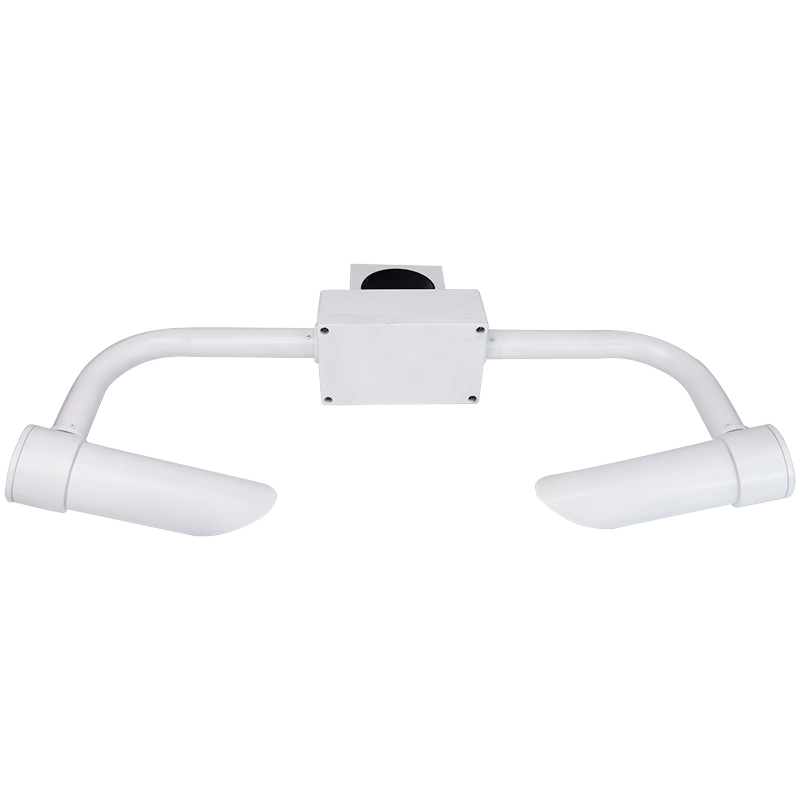
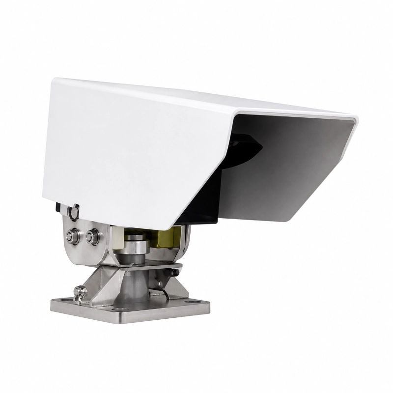
For applications requiring continuous fixed monitoring rather than portable inspection, a dedicated visibility sensor for road and tunnel monitoring can be integrated into a permanent road weather or traffic monitoring network.
Portable Meter vs Fixed Tunnel Visibility Sensor
Comparison
Portable Transmittance Meter
Fixed Visibility Sensor
Temporary field testing
Suitable
Limited
Continuous 24-hour monitoring
No
Suitable
Multi-point inspection
Suitable
Requires multiple devices
Easy relocation
Yes
No
Automatic alarm output
Configuration-dependent
Common
Tunnel-control integration
Limited
Suitable
Acceptance inspection
Suitable
Can support
Fixed ventilation control
Not primary use
Suitable
Field verification
Suitable
Device being verified
Installation work
Lower
Higher
Choose a portable transmittance meter when:
Multiple tunnel points must be checked;
The project requires temporary testing;
A fixed sensor must be verified;
The user needs an inspection tool;
Permanent wiring is unavailable.
Choose a fixed visibility detector when:
Continuous data is required;
Automatic ventilation control is required;
Alarms must operate continuously;
Data must be transmitted to a tunnel control centre.
For continuous outdoor or road-weather visibility monitoring, see the Visibility Sensor 10 km RS485 Modbus for Weather Monitoring. The JW-CQ10(YN09) is a fixed optical forward-scattering visibility sensor for real-time meteorological optical-range measurement.
Technical Specifications
Parameter
Specification
Model
JW-TRA10(HY04)
Transmittance Range T
0 to 100%
Visibility Range VI
1 to 5000 m
Smoke Concentration Range K
0 to 35 × 10⁻³ 1 m
CO Concentration Range
0 to 300 ppm
Tunnel Environment Temperature
-40°C to +80°C
Tunnel Environment Humidity
0 to 100%
Display
128 × 64 dot matrix LCD with numeric and text display
Measuring Principle
Light transmittance method digital probe electrochemical probe
Measurement Error
±2% transmittance full scale
Ambient Temperature
-55°C to +65°C
Ambient Humidity
0 to 100% RH
Communication Interface
RS232 RS485 USB
Power Supply
AC 220V power adapter with built-in rechargeable battery
Battery Endurance
More than 10 hours without external power
Data Storage
Up to 70 hours of continuous test data
Detection Cycle
2 s customizable
Storage Cycle
10 s local storage
Total Weight
16 kg including instrument instrument case and mounting support
Typical Applications
Road Tunnel Inspection
The meter can be used to compare visibility-related conditions at:
Tunnel entrances
Tunnel exits
Mid-tunnel sections
Uphill sections
Downhill sections
Ventilation zones
Emergency bays
High-traffic sections
Areas near exhaust accumulation
Ventilation Performance Assessment
Measurements can be taken before and after:
Starting jet fans
Changing ventilation modes
Increasing airflow
Cleaning ventilation equipment
Modifying traffic control
Completing maintenance work
The results can help operators compare relative improvements under controlled test conditions.
Fixed Sensor Verification
The portable meter may be used as an independent field reference for checking whether a permanently installed tunnel visibility sensor shows a consistent trend.
This does not replace formal calibration unless the portable instrument and procedure meet the required calibration standard.
Tunnel Acceptance Testing
Engineering teams may use portable measurements during:
New tunnel commissioning
Ventilation-system acceptance
Lighting-system assessment
Safety-system testing
Renovation completion
Equipment replacement
The final acceptance method should follow the project specification and local regulatory requirements.
Cleaning Effect Evaluation
Tunnel wall, lamp and optical equipment contamination may affect visual conditions.
Measurements before and after cleaning can support comparison, provided:
The same location is used;
The same path length is used;
Traffic and ventilation conditions are recorded;
Optical windows are clean;
The measurement method remains consistent.
Incident and Emergency Inspection
After smoke, fire, construction work or abnormal emissions, a portable meter can support temporary inspection before normal operation resumes.
It should be used as one part of the safety assessment rather than the only basis for reopening a tunnel.
Underground Parking and Enclosed Roads
The meter may also be used in:
Underground parking areas
Enclosed road sections
Vehicle inspection passages
Underground logistics tunnels
Mining access tunnels
Large indoor traffic facilities
How to Use the Portable Transmittance Meter
1. Select the Measurement Location
Choose a position that represents the inspection objective.
Possible locations include:
Portal areas
Tunnel centre
High-emission sections
Ventilation zones
Areas with poor historical visibility
Fixed sensor locations
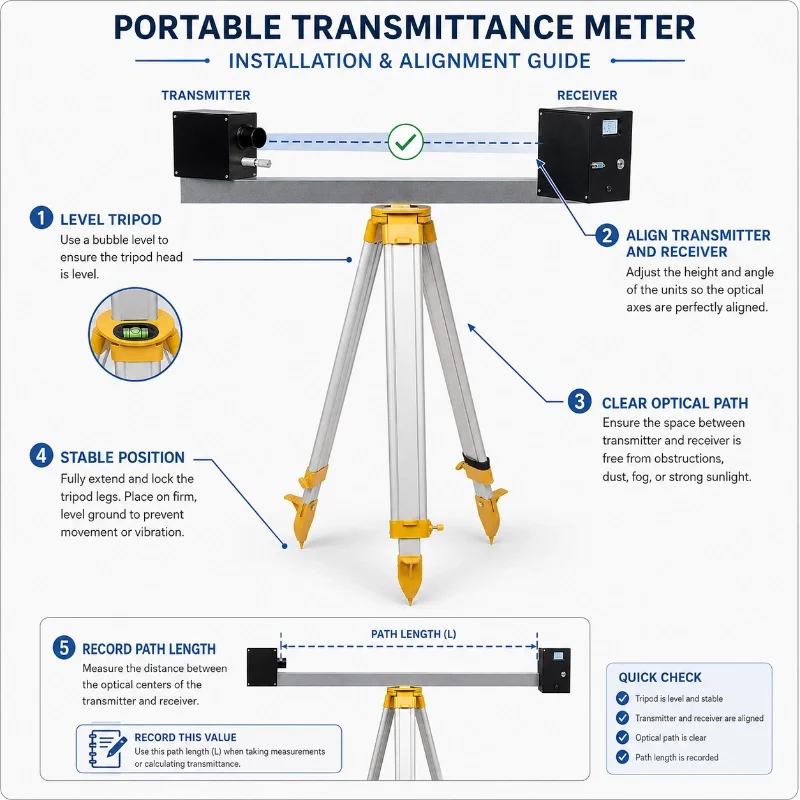
2. Establish a Clear Optical Path
Position the transmitter and receiver so that:
They face each other;
They are on the same optical axis;
The path is not blocked by walls or equipment;
The selected distance matches the test procedure.
3. Confirm the Measurement Distance
Record the optical path length.
Transmittance measured over one distance should not be directly compared with a result measured over a different distance without applying an approved conversion method.
4. Clean the Optical Windows
Inspect the transmitter and receiver windows before testing.
Remove:
Dust
Fingerprints
Water droplets
Oil
Condensation
Tunnel deposits
5. Perform the Required Reference Check
Follow the product manual for:
Zero adjustment
Reference setting
Self-check
Baseline confirmation
Warm-up procedure
Do not invent or use a calibration sequence that is not specified for the actual instrument.
6. Wait for a Stable Reading
Allow the displayed value to stabilize.
Avoid recording a value during:
Vehicle obstruction
Sudden exhaust plume
Personnel crossing the optical path
Fan switching
Instrument movement
7. Record Supporting Conditions
For each test, record:
Tunnel name
Measurement position
Date and time
Optical path length
Traffic volume
Ventilation status
Temperature and humidity
Visible smoke or mist
Instrument serial number
Operator
Repeated readings
8. Repeat the Measurement
Repeat testing at the same point and compare the readings.
Multiple readings are more useful than one isolated value when the tunnel environment is changing.
For long tunnels, use multiple measurement sections rather than assuming one reading represents the entire tunnel.
Factors That Can Affect Accuracy
Optical Misalignment
If the transmitter and receiver are not correctly aligned, the receiver may collect less light and report an artificially low value.
Dirty Optical Windows
Dust, moisture and deposits on the optical window may be interpreted as atmospheric attenuation.
Vehicle Obstruction
A vehicle passing through the beam can temporarily block the optical path.
Direct Lighting Interference
Strong tunnel lights or headlights may affect the optical receiver if the instrument is not positioned correctly.
Inconsistent Path Length
Changing the measurement distance makes direct comparison difficult.
Non-Uniform Smoke or Dust
Smoke and exhaust may be concentrated in one part of the tunnel, especially near the ceiling, road surface or traffic lane.
Condensation
Condensation on the optics can significantly affect the result.
Instrument Movement
Vibration or movement during measurement can affect alignment.
Insufficient Stabilization
A reading taken before the instrument stabilizes may not represent the actual condition.
Installation and Positioning Recommendations
Although the product is portable, temporary positioning still affects the result.
Recommended practices include:
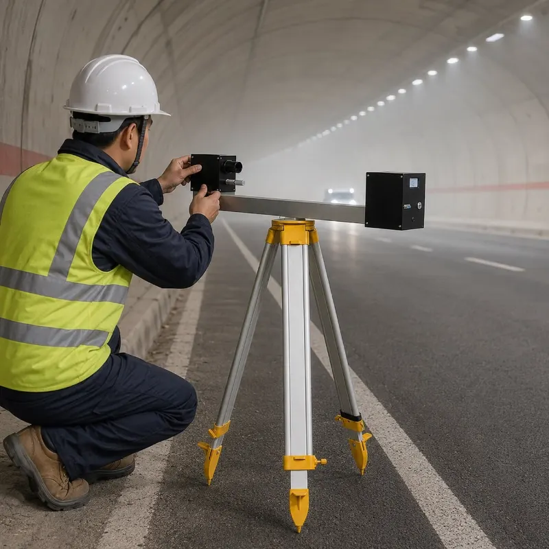
Use a stable tripod or support;
Keep transmitter and receiver at the same height;
Avoid placing the optical path directly behind a vehicle exhaust;
Avoid direct alignment with high-intensity lamps;
Keep the instruments away from water spray;
Protect cables from vehicle lanes;
Use safety cones and traffic-management procedures;
Do not leave equipment unattended in an active lane;
Use reflective clothing and follow tunnel-safety rules.
Data Interpretation
A transmittance reading should be interpreted together with:
Optical path length
Traffic conditions
Ventilation status
Time of measurement
Location
Temperature
Humidity
Smoke or dust source
Fixed-sensor data
Camera images
Historical readings
Useful comparisons include:
Before and after ventilation adjustment
Before and after tunnel cleaning
Low-traffic and high-traffic periods
Portal and mid-tunnel sections
Portable meter and fixed sensor trends
Normal and incident conditions
Portable Transmittance Meter vs Haze Meter
A material haze meter is normally used to test transparent materials such as plastic, glass or film.
A tunnel transmittance meter measures light attenuation through an air path containing smoke, dust or aerosols.
They should not be treated as interchangeable instruments.
Requirement
Tunnel Transmittance Meter
Material Haze Meter
Air-path measurement
Yes
No
Tunnel smoke assessment
Suitable
Not suitable
Glass or plastic haze testing
Not primary use
Suitable
Long optical path
Configurable
Usually short sample path
Field tunnel inspection
Suitable
Limited
Material laboratory testing
No
Suitable
Maintenance Recommendations
Regularly inspect:
Optical windows
Alignment components
Cables
Connectors
Battery
Display
Tripod or support
Carrying case
Reference accessories
Calibration status
Instrument housing
After tunnel use:
Clean the optical surfaces;
Dry any moisture;
Check the lens covers;
Recharge or replace the battery;
Save or export test records;
Store the instrument in its protective case.
A portable meter is better suited to field inspection and temporary verification.
How to Choose Equipment for Tunnel Visibility Monitoring
The appropriate visibility monitoring equipment depends mainly on whether the project requires temporary inspection or continuous monitoring.
Choose a portable transmittance meter when the project requires:
Tunnel acceptance testing
Temporary inspection
Multi-point field measurements
Portable road visibility testing
Transmittance measurements
VI and CO inspection
Local data storage and later export
Choose a fixed visibility sensor when the project requires:
Continuous 24/7 visibility monitoring
Permanent roadside or tunnel installation
Automatic RS485 Modbus data collection
Integration with an RTU or IoT gateway
Remote monitoring and cloud platforms
Automatic warning or traffic-management systems
Choose an integrated road weather station when visibility data must be combined with multiple road and meteorological parameters within the same monitoring network.
Project configuration should therefore be based on the monitoring objective, installation environment, required parameters, data transmission method, number of monitoring points, and whether measurement is temporary or continuous.
JW-IoT can support both portable inspection instruments and fixed monitoring hardware for road, highway, bridge, and tunnel projects.
Request a Portable Tunnel Visibility Meter
Send JW-IoT your tunnel length, required measurement points, optical-path requirements, inspection method and calibration requirements.
Our team will help recommend a suitable portable transmittance meter or fixed tunnel visibility monitoring configuration.
1. What does JW-TRA10(HY04) portable transmittance meter measure?
A
It measures atmospheric transmittance, road visibility, tunnel smoke concentration, CO concentration, and tunnel temperature and humidity.
Q
2. Is JW-TRA10(HY04) suitable for tunnel acceptance testing?
A
Yes. It is suitable for tunnel VI and CO acceptance testing, as well as temperature and humidity measurement in tunnel environments.
Q
3. Can JW-IoT provide this portable transmittance meter for tunnel projects?
A
Yes. JW-IoT can provide JW-TRA10(HY04) portable transmittance meter for tunnel monitoring, road visibility testing, and related environmental measurement projects.
Q
4. Does the device need complicated installation before use?
A
No. One of its main advantages is easy operation. It does not require complex installation or commissioning and can start testing after power-on.
Q
5. How is the data stored and exported?
A
The instrument has built-in storage and can automatically save test data. After testing, users can connect it to a computer and export data through the software in Excel format.
Q
6. Does JW-IoT support data logging solutions for field testing?
A
Yes. JW-IoT supports instruments with internal data logging functions, helping customers collect, store, and export field measurement data more efficiently.
Q
7. How long can the instrument work without external power?
A
With its built-in rechargeable battery, the device can work continuously for more than 10 hours without an external power supply.
Q
8. What communication interfaces are available?
A
JW-TRA10(HY04) supports RS232, RS485, and USB communication interfaces.
JW-IoT portable transmittance meters are designed for convenient field use, reliable testing, internal data storage, and practical export functions, making them suitable for road and tunnel monitoring applications.
 +86 13520127780
  info@jingelway.com