+86 13520127780
  info@jingelway.com








Why Accurate Irradiance Measurement Is Critical for PV Plants
Release time: 2026-08-02
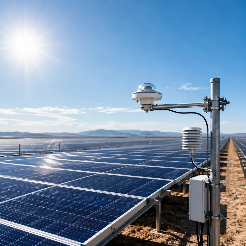
Solar photovoltaic power generation depends on one environmental input above all others: sunlight.
However, knowing how much electricity a PV plant produces is not enough to determine whether it is operating efficiently. A reduction in power output may be caused by lower solar irradiance, cloud cover, high module temperature, dust accumulation, shading, inverter faults, electrical losses, or module degradation.
Without accurate on-site solar irradiance measurement, operators cannot reliably separate weather-related production changes from actual system underperformance.
For this reason, solar irradiance sensors are essential components of modern PV monitoring systems. They provide the environmental baseline required for performance ratio calculation, energy-yield assessment, fault diagnosis, contractual reporting, and long-term operation and maintenance.
This article explains how irradiance is measured, why measurement accuracy affects PV plant performance analysis, which sensor types are commonly used, and how to configure a reliable irradiance monitoring system.
What Is Solar Irradiance Measurement?
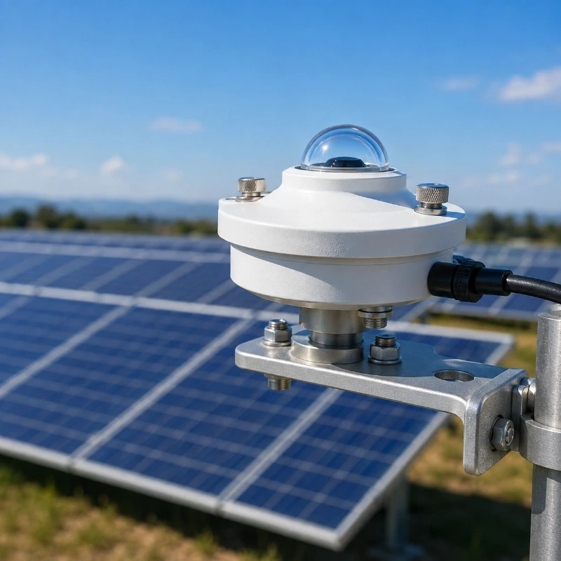
Solar irradiance measurement is the process of measuring the instantaneous solar power received by a surface per unit area.
It is normally expressed in watts per square meter:
W/m²
Solar irradiance should not be confused with solar irradiation.
- Irradiance describes the instantaneous power of incoming solar radiation, measured in W/m².
- Irradiation describes the accumulated solar energy received over a period, commonly measured in Wh/m² or kWh/m².
For example, an irradiance sensor may record a value of 850 W/m² at a particular moment. When those readings are integrated over the day, the monitoring system can calculate the total daily solar irradiation.
In a PV plant, irradiance measurements are generally collected by a pyranometer, silicon reference cell, or other solar radiation sensor. The sensor is connected to a data logger, RTU, PLC, weather station controller, inverter monitoring system, or cloud-based monitoring platform.
Depending on the monitoring objective, a plant may measure:
Global Horizontal Irradiance
Global horizontal irradiance, or GHI, measures the total solar radiation received by a horizontal surface.
GHI is useful for:
- General solar resource monitoring
- Weather station data collection
- Comparing local conditions with regional data
- Long-term solar resource assessment
- Supporting horizontal or low-tilt PV analysis
Plane-of-Array Irradiance
Plane-of-array irradiance, or POA irradiance, measures solar radiation on the same plane and at the same tilt angle as the PV modules.
POA measurement is particularly important for PV performance analysis because it more closely represents the solar energy available to the module surface.
Direct, Diffuse, and Reflected Irradiance
More advanced monitoring systems may separately evaluate:
- Direct solar radiation
- Diffuse sky radiation
- Ground-reflected radiation
- Rear-side irradiance for bifacial PV modules
The required configuration depends on the plant design, module technology, tracker type, terrain, performance guarantee, and monitoring accuracy target.
Explore the JW-IoT Solar Irradiance Sensor for PV Monitoring Solution for configurable on-site radiation measurement.
Why Irradiance Is the Baseline of PV Plant Performance
PV power output changes continuously as solar radiation changes.
When irradiance rises, the potential output of a PV array normally increases. When irradiance falls because of clouds, haze, shading, or rainfall, power generation also decreases.
This means that electrical output alone cannot show whether a plant is performing normally.
Consider a 50 MW solar plant producing only 35 MW during the middle of the day. That figure may indicate a serious performance problem, or it may be completely normal under reduced irradiance.
To make a meaningful assessment, the monitoring platform must compare actual power generation with the solar energy available at the site.
Accurate irradiance data allows plant operators to:
- Normalize energy production against changing weather conditions
- Compare actual output with expected output
- Calculate and trend performance ratio
- Identify abnormal energy losses
- Compare different arrays, inverter blocks, or plant zones
- Evaluate the impact of module temperature
- Detect shading, soiling, and equipment faults
- Verify performance guarantees
- Support O&M and asset-management reports
In practical terms, the irradiance sensor acts as the environmental reference point for the entire PV performance monitoring process.
How Inaccurate Irradiance Affects PR Analysis
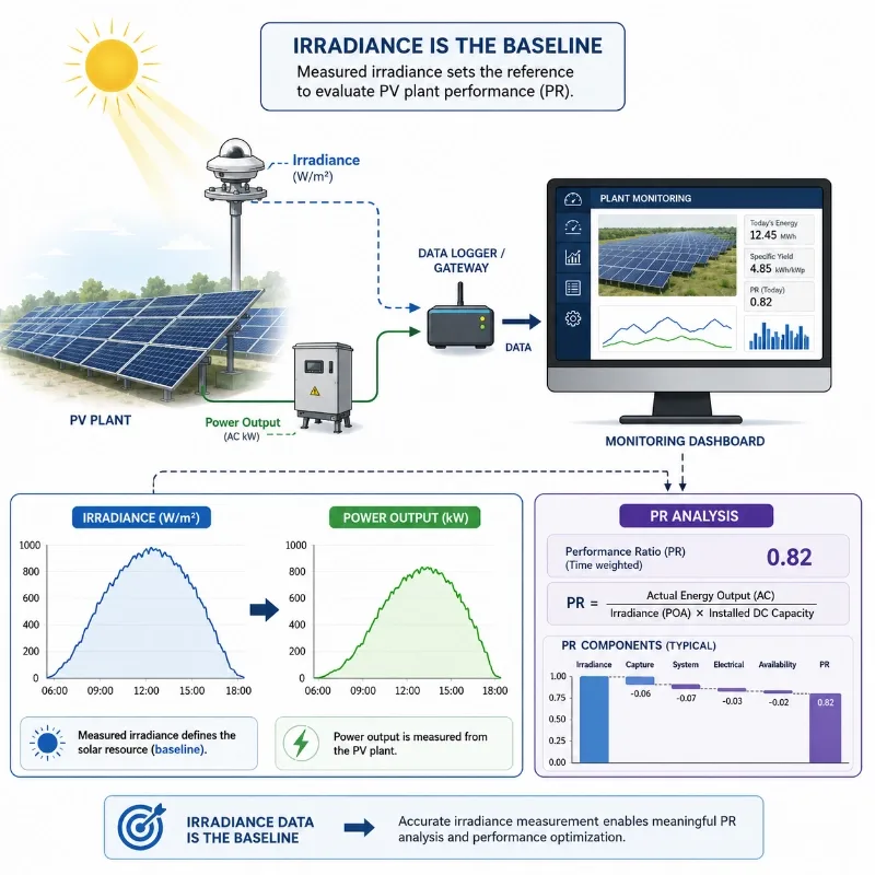
Performance ratio, usually abbreviated as PR, is one of the most widely used indicators for evaluating PV plant performance.
PR compares the actual energy output of a PV system with the theoretical output expected from the available solar resource and installed capacity.
A simplified representation is:
Performance Ratio = Final System Yield ÷ Reference Yield
The reference yield depends directly on measured solar irradiation. Therefore, any irradiance measurement error can influence the calculated PR.
Overestimated Irradiance
When the sensor reports more irradiance than the PV modules actually receive, the monitoring system assumes that more solar energy was available.
The calculated PR may then appear lower than the plant’s true performance.
This can lead to:
- False underperformance alarms
- Unnecessary inverter or module inspections
- Incorrect warranty or contractual claims
- Misleading comparisons between plant zones
- Distorted O&M performance reports
Underestimated Irradiance
When the sensor reports less irradiance than the array actually receives, the calculated PR may appear artificially high.
This can hide:
- Module degradation
- Inverter efficiency loss
- Cable and connection losses
- Partial shading
- Soiling-related production loss
- String or combiner-box faults
An apparently strong PR is not necessarily evidence of strong plant performance when the irradiance baseline is inaccurate.
Example of Irradiance Measurement Error
Suppose a PV plant produces the expected electrical yield for a day, but its irradiance sensor underreports daily irradiation by 5%.
Because the reference solar input is too low, the calculated PR will be inflated. Plant operators may conclude that the system is performing better than it actually is.
The opposite occurs when irradiance is overreported. A healthy plant may appear to be underperforming.
For large utility-scale plants, even relatively small measurement biases can influence performance reporting, maintenance priorities, revenue evaluation, and contractual decisions.
Irradiance Data for PV Fault Diagnosis
Accurate solar irradiance measurement does more than support PR calculation. It also helps operators determine why production has changed.
By comparing irradiance, module temperature, inverter output, and electrical data, a monitoring platform can identify different performance patterns.
Normal Weather-Related Reduction
When irradiance and PV output fall at the same time and by a similar proportion, the reduction is likely related to clouds, haze, or other weather conditions.
Possible Equipment Fault
When irradiance remains stable but the output of an inverter block or array drops suddenly, the system may have:
- An inverter fault
- A disconnected string
- A combiner-box problem
- Cable damage
- Grid curtailment
- Communication failure
Possible Soiling or Shading
When irradiance remains normal but output gradually decreases relative to the reference, the cause may be:
- Dust accumulation
- Bird droppings
- Vegetation shading
- New structural shading
- Uneven cleaning
- Sensor or module contamination
Possible Temperature Loss
When irradiance is high but module temperature increases significantly, the PV conversion efficiency may decrease.
Combining a solar irradiance sensor with one or more module temperature sensors makes it easier to separate temperature-related loss from other electrical or environmental problems.
JW-IoT provides complete Solar PV Monitoring Solutions that can combine irradiance, module temperature, weather, inverter, and power-generation data.
Irradiance Sensor Types for PV Plants
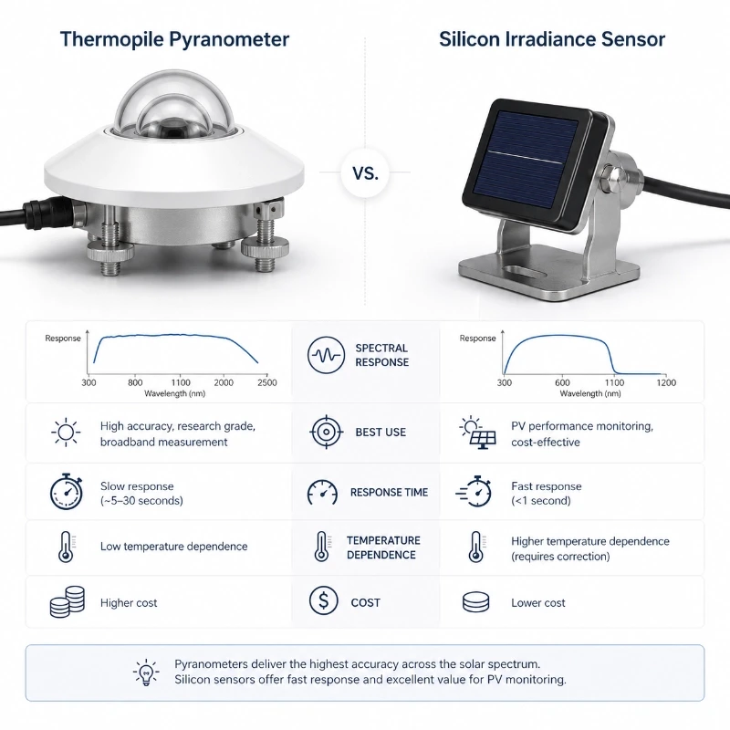
Different irradiance sensors have different spectral responses, response times, uncertainty levels, installation requirements, and project costs.
The most common options for PV monitoring include thermopile pyranometers and silicon irradiance sensors.
Thermopile Pyranometers
A thermopile pyranometer measures broadband solar radiation using a radiation-absorbing surface and thermoelectric sensing structure.
It is commonly used for:
- Utility-scale PV plants
- Professional PV weather stations
- Meteorological monitoring
- Solar resource assessment
- Performance testing
- Projects requiring broad spectral measurement
Advantages
- Broad spectral response
- Suitable for global solar radiation measurement
- Strong compatibility with professional PV monitoring
- Available in different accuracy classes
- Suitable for horizontal and plane-of-array installation
Considerations
- Generally costs more than a silicon sensor
- Requires careful leveling and orientation
- The glass dome must be kept clean
- Calibration and maintenance must be managed
- Thermal offsets and response time should be considered
For professional applications, a higher-grade pyranometer may be selected when measurement uncertainty, contractual reporting, or compliance requirements are particularly important.
View the Class A Pyranometer Solar Radiation Sensor with RS485 Output.
Silicon Irradiance Sensors
A silicon irradiance sensor uses a photovoltaic reference cell or silicon sensing element to measure incoming solar radiation.
Its spectral response is closer to that of conventional crystalline-silicon PV modules than that of a broadband thermopile pyranometer.
It is commonly used for:
- Plane-of-array irradiance monitoring
- Distributed PV plants
- Commercial rooftop systems
- Array-level performance comparison
- Compact PV weather stations
- Cost-sensitive multi-point monitoring
Advantages
- Fast response to changing irradiance
- Compact and easy to install
- Spectral response similar to silicon PV modules
- Suitable for mounting in the same plane as the array
- Practical for multiple monitoring points
- Easy integration with RS485 Modbus systems
Considerations
- Spectral range is narrower than a thermopile pyranometer
- Temperature compensation is important
- Sensor selection should consider the PV module technology
- Long-term stability and calibration must be evaluated
For many operational PV monitoring projects, silicon sensors provide a practical balance of response speed, installation convenience, and cost.
Learn more about the Silicon Irradiance Sensor for PV Performance Monitoring.
Thermopile Pyranometer or Silicon Sensor?
There is no single sensor type that is best for every PV project.
A thermopile pyranometer is generally more suitable when:
- Broadband solar radiation measurement is required
- The data will support formal performance assessment
- Measurement uncertainty must be minimized
- Different PV module technologies are installed
- The station is used for meteorological or solar resource analysis
A silicon irradiance sensor may be more suitable when:
- The main objective is operational PV performance monitoring
- Fast response is important
- The sensor will be mounted in the array plane
- Multiple monitoring points are needed
- The PV modules use similar silicon technology
- The project requires a more economical configuration
Many large PV plants use both types: a high-quality pyranometer as a primary reference and silicon sensors for additional array-level or zone-level measurements.
Installation Considerations for Accurate Measurement
Even a high-quality sensor can produce unreliable data when installed incorrectly.
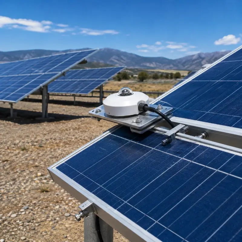
The following factors should be considered during sensor installation.
Match the Sensor Plane to the Measurement Objective
A GHI sensor should be installed horizontally and properly leveled.
A POA sensor should match the tilt and azimuth of the PV modules being evaluated. Even a small alignment difference may create a systematic difference between the irradiance reaching the sensor and the irradiance reaching the modules.
For tracking systems, the sensor mounting method must allow it to follow the array position correctly.
Avoid Local Shading
The sensor should not be shaded by:
- PV modules
- Mounting structures
- Poles
- Cable trays
- Weather station components
- Nearby buildings
- Trees or vegetation
Shadows that affect the sensor but not the modules—or affect the modules but not the sensor—can distort performance analysis.
Select a Representative Location
The sensor should represent the actual conditions of the monitored array.
A single sensor may not adequately represent a large plant with:
- Different terrain elevations
- Multiple module orientations
- Separate tracker zones
- Uneven cloud movement
- Different soiling conditions
- Long distances between array sections
Large or geographically complex plants may require multiple irradiance monitoring points.
Maintain Correct Orientation
For fixed-tilt systems, the POA sensor should match the module tilt and azimuth.
For single-axis trackers, the sensor should be mounted so that it moves consistently with the tracker.
For bifacial systems, rear irradiance measurement may require several sensors positioned at representative locations behind the array.
Prevent Water Accumulation and Cable Problems
The mounting structure should provide:
- Secure mechanical fixation
- Suitable cable protection
- Weather-resistant connectors
- Appropriate cable routing
- Protection against water ingress
- Stable grounding and surge protection where required
RS485 communication cables should be installed according to the project’s grounding, shielding, and termination requirements.
Cleaning, Inspection, and Calibration
Dust, pollen, salt, snow, bird droppings, and other contaminants can reduce the radiation reaching the sensing surface.
If the irradiance sensor becomes dirtier than the PV modules, the system may underestimate the irradiance available to the array. If the sensor is cleaner than the modules, soiling-related production loss may become more visible, but the cleaning strategy must remain consistent and documented.
A maintenance plan should include:
- Regular visual inspection
- Cleaning of domes or sensing surfaces
- Checking sensor level and orientation
- Inspecting connectors and cables
- Verifying communication and data quality
- Reviewing nighttime offsets
- Detecting sudden measurement drift
- Comparing redundant sensors
- Periodic calibration according to project requirements
Calibration records should include the sensor identification number, calibration date, calibration factor, calibration method, and next recommended calibration date.
Replacing or recalibrating a sensor without updating the data logger configuration can introduce a new measurement bias. Any calibration coefficient must therefore be entered correctly into the acquisition and monitoring system.
Data Acquisition and Quality Control
Reliable PV monitoring requires more than a good sensor.
The complete measurement chain includes:
Irradiance sensor → signal output → data logger or RTU → communication network → monitoring platform → PR and fault analysis
Errors can occur at any stage.
Common data problems include:
- Incorrect Modbus register mapping
- Wrong unit conversion
- Incorrect calibration coefficient
- Timestamp mismatch
- Missing records
- Communication interruptions
- Sensor saturation
- Negative daytime values
- Non-zero nighttime readings
- Unrealistic spikes
- Duplicate data
- Averaging intervals that do not match electrical data
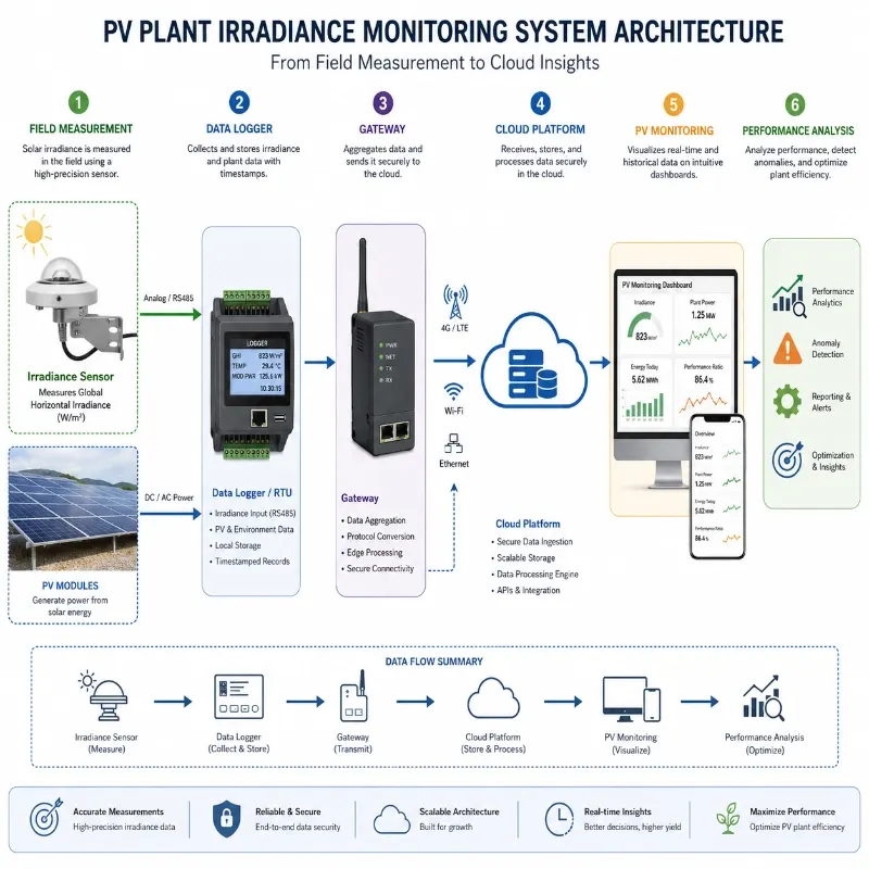
The irradiance data and PV output data should use synchronized timestamps and compatible sampling or averaging intervals.
A monitoring platform should also apply data-quality rules to identify:
- Values outside the expected range
- Frozen sensor readings
- Sudden step changes
- Missing data
- Irradiance recorded at night
- Differences between redundant sensors
- Inconsistent irradiance and power trends
Reliable data validation reduces false alarms and prevents invalid readings from distorting PR reports.
Recommended Irradiance Sensor Configuration
The final configuration should be based on plant capacity, layout, terrain, module technology, monitoring objectives, accuracy requirements, and budget.
Distributed Rooftop PV System
A practical configuration may include:
- One silicon POA irradiance sensor
- One PV module temperature sensor
- Ambient temperature and humidity monitoring
- Compact RS485 data logger
- 4G or Ethernet communication
- Cloud or local monitoring platform
This configuration supports basic PR analysis, performance comparison, and fault detection for commercial and industrial rooftops.
Medium-Sized Ground-Mounted PV Plant
A typical system may include:
- One horizontal thermopile pyranometer
- One or more POA irradiance sensors
- Multiple module temperature sensors
- Ambient temperature and humidity
- Wind speed and direction
- Rainfall monitoring
- Data logger or RTU
- 4G, Ethernet, or LoRaWAN communication
- Centralized monitoring platform
Utility-Scale PV Plant
A utility-scale configuration may include:
- High-quality horizontal reference pyranometer
- Multiple POA irradiance sensors
- Redundant reference sensors
- Irradiance monitoring in different plant zones
- Module temperature sensors on representative arrays
- Ambient temperature and humidity sensors
- Wind speed and direction monitoring
- Rainfall and atmospheric pressure
- Soiling monitoring
- Inverter and electricity-meter integration
- Industrial data logger and edge gateway
- Central cloud or SCADA integration
The number of monitoring points should be determined by plant layout, terrain variation, module orientation, tracker configuration, local weather variability, and contractual requirements.
Bifacial PV Plant
Bifacial systems may additionally require:
- Front-side POA irradiance
- Rear-side irradiance
- Multiple rear sensors across representative positions
- Albedo or reflected-radiation monitoring
- Module temperature
- Soiling monitoring
- Tracker position data
Rear irradiance can vary significantly with sensor height, row spacing, ground surface, shading, and mounting geometry. Sensor placement should therefore reflect the actual array design.
Integrating Irradiance with a PV Weather Station
Solar irradiance is the most important environmental baseline, but it should not be analyzed in isolation.
A complete PV plant weather station can monitor:
- Global horizontal irradiance
- Plane-of-array irradiance
- Accumulated solar irradiation
- PV module temperature
- Ambient temperature
- Relative humidity
- Wind speed
- Wind direction
- Rainfall
- Atmospheric pressure
- Optional soiling or dust conditions
Combining these parameters helps operators distinguish among resource variation, thermal loss, weather risk, soiling, and electrical underperformance.
Explore the JW-IoT PV Plant Weather Station Solution or view the Solar PV Weather Station for Power Plant Monitoring.
Why Use On-Site Irradiance Instead of Regional Weather Data?
Satellite databases and regional weather stations are useful for preliminary resource assessment and benchmarking, but they may not represent the exact conditions at a PV plant.
Differences may result from:
- Local cloud movement
- Terrain and elevation
- Coastal haze
- Dust events
- Nearby industrial emissions
- Mountain shadows
- Snow cover
- Local rainfall
- Array orientation
- Microclimate conditions
Regional data may also have a different spatial resolution, timestamp, or measurement plane.
For operational performance analysis, on-site irradiance measurement provides the closest representation of the solar resource actually available to the PV modules.
External datasets can still be used as secondary references, but they should not automatically replace properly maintained field sensors.
Building a Reliable PV Monitoring System
Accurate solar irradiance measurement gives PV operators a defensible baseline for evaluating plant performance.
A well-designed monitoring system can help answer questions such as:
- Is lower production caused by weather or equipment?
- Is the plant meeting its expected performance ratio?
- Which inverter block is underperforming?
- Is module temperature reducing efficiency?
- Has soiling reached the point where cleaning is justified?
- Are different array zones receiving different irradiance?
- Is a sensor drifting or producing invalid data?
- Does the plant need additional monitoring points?
The quality of these answers depends on the complete monitoring chain—not only the nominal accuracy of the sensor.
Correct sensor selection, representative installation, regular cleaning, traceable calibration, synchronized data collection, and automated data-quality checks are all essential.
Conclusion
Accurate solar irradiance measurement is fundamental to reliable PV plant monitoring.
Irradiance provides the environmental reference required to calculate performance ratio, normalize energy production, detect abnormal losses, compare plant zones, and distinguish weather-related changes from equipment faults.
Selecting the right sensor is only the first step. The sensor must also be installed in the correct plane, positioned in a representative location, kept clean, calibrated appropriately, and integrated with a reliable data acquisition and monitoring system.
JW-IoT supplies solar irradiance sensors, silicon reference sensors, thermopile pyranometers, PV weather stations, data loggers, communication devices, and remote monitoring solutions for rooftop, distributed, utility-scale, floating, and bifacial PV projects.
Get an Irradiance Sensor Quote
Send JW-IoT the following project information:
- PV plant capacity
- Fixed-tilt or tracking structure
- Module type
- Required GHI or POA measurement
- Number of monitoring locations
- Required sensor accuracy
- Output signal or communication protocol
- Data logger or platform requirements
- Power-supply conditions
- Installation environment
Our technical team can recommend an appropriate sensor and system configuration for your project.
Frequently Asked Questions
1. What is solar irradiance measurement in a PV plant?
Solar irradiance measurement determines the instantaneous solar power received by a surface, normally expressed in W/m². In a PV plant, it provides the baseline needed to compare available sunlight with actual electricity generation.
2. Why is irradiance important for performance ratio calculation?
The performance ratio compares actual PV energy output with the output expected from the available solar resource. Because the reference yield is derived from irradiance, inaccurate irradiance data can directly distort the calculated PR.
3. What is the difference between GHI and POA irradiance?
GHI measures solar radiation on a horizontal surface. POA irradiance measures radiation in the same plane as the PV modules. POA is usually more directly relevant to array-level performance analysis.
4. Which sensor is suitable for a PV power plant?
Thermopile pyranometers are commonly used for broadband, professional, and higher-accuracy measurements. Silicon irradiance sensors are often selected for fast-response POA monitoring and economical multi-point deployment.
5. Can a silicon sensor replace a thermopile pyranometer?
It depends on the project objective and accuracy requirement. A silicon sensor may be suitable for operational PV performance monitoring, while a thermopile pyranometer is often preferred for broadband solar resource measurement or formal performance assessment.
6. How often should an irradiance sensor be calibrated?
The calibration interval should follow the sensor manufacturer’s recommendations, the project’s quality plan, applicable monitoring requirements, and the importance of the data. Sensors should also be inspected for drift between formal calibrations.
7. How many irradiance sensors does a PV plant need?
The required number depends on plant size, terrain, module orientation, tracker layout, local weather variability, and monitoring requirements. Large or complex sites usually require multiple sensors in representative zones.
8. Can regional weather data replace an on-site irradiance sensor?
Regional and satellite data can support benchmarking and resource assessment, but they may not represent the exact irradiance received at the PV array. On-site sensors are generally more appropriate for operational PR analysis and fault diagnosis.
9. Can JW-IoT integrate irradiance sensors with an existing platform?
Yes. JW-IoT sensors and monitoring devices can support common interfaces such as RS485 Modbus and can be integrated with data loggers, RTUs, PLCs, gateways, cloud platforms, or selected third-party monitoring systems according to project requirements.