+86 13520127780
  info@jingelway.com








PV Module Temperature Monitoring for Extreme Climates
Release time: 2026-08-04
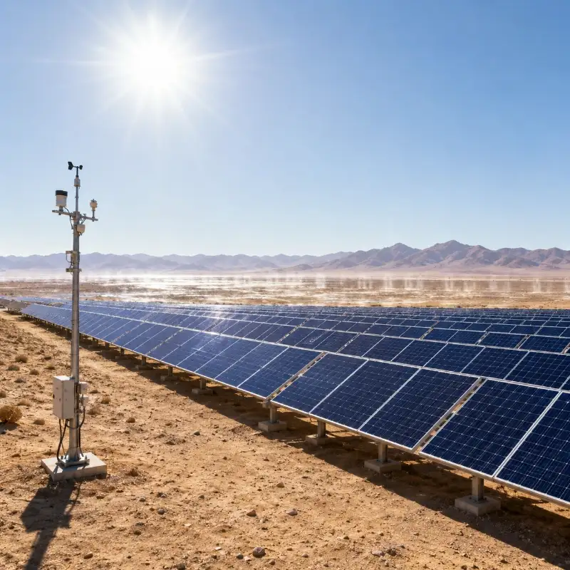
Solar PV plants operating in deserts, tropical regions, high-altitude areas, and other extreme climates face environmental conditions that can significantly affect power generation.
High solar irradiance is generally beneficial for solar energy production. However, strong sunlight can also raise the operating temperature of PV modules far above the surrounding air temperature. As module temperature increases, the electrical efficiency of most conventional PV modules decreases.
This creates an important monitoring challenge.
A PV plant may receive excellent solar irradiance while producing less power than expected because the modules are operating at an excessively high temperature. Without accurate PV module temperature monitoring, operators may incorrectly attribute the production loss to dust, inverter performance, module degradation, or inaccurate irradiance data.
A properly installed solar panel temperature sensor allows plant operators to evaluate thermal losses, improve performance ratio analysis, compare different array zones, and identify abnormal heating before it develops into a more serious operational problem.
This guide explains why extreme climates affect PV performance, how module temperature influences electrical output, where temperature sensors should be installed, and how temperature data can be integrated with a complete PV weather monitoring system.
Why Extreme Climates Affect PV Performance
PV modules are designed for long-term outdoor operation, but their real-world performance depends heavily on the surrounding environment.
Extreme climates may expose a solar plant to:
- High daytime air temperatures
- Strong solar irradiance
- Large day-to-night temperature differences
- Dust and sand accumulation
- Hot, dry winds
- Limited natural cooling
- High humidity or salt mist
- Heavy rainfall and rapid cooling
- Snow, frost, or freezing conditions
- High ultraviolet exposure
- Strong wind and mechanical stress
These environmental factors do not affect every solar plant in the same way.
A desert PV plant may experience very high module temperatures, frequent dust deposition, abrasive wind-blown sand, and large temperature changes between daytime and nighttime.
A tropical solar installation may face high ambient temperature, high humidity, intense rainfall, limited ventilation, and biological contamination.
A high-altitude PV plant may receive strong irradiance and ultraviolet radiation while also experiencing low air temperature, snow, frost, and rapid weather changes.
For this reason, extreme climate solar monitoring should not rely on power-generation data alone. Operators need to combine electrical data with on-site environmental measurements.
The most useful parameters commonly include:
- Plane-of-array solar irradiance
- Global horizontal irradiance
- PV module temperature
- Ambient air temperature
- Relative humidity
- Wind speed
- Wind direction
- Rainfall
- Atmospheric pressure
- Soiling or dust-loss data
Together, these parameters help explain whether a change in power generation is caused by available sunlight, high module temperature, dust accumulation, weather conditions, or an electrical fault.
How Module Temperature Impacts PV Output
PV modules convert solar radiation into electrical energy. However, not all incoming solar energy becomes electricity.
Part of the absorbed solar energy is converted into heat. This causes the module temperature to rise above the surrounding air temperature, especially during periods of strong irradiance and low wind speed.
The relationship can be summarized as follows:
Higher irradiance → higher module temperature → lower electrical conversion efficiency
The exact temperature response depends on the module technology and its specified temperature coefficient.
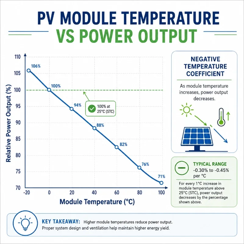
Manufacturers normally provide a power temperature coefficient on the module datasheet. This value indicates how much the module’s maximum power changes for every degree Celsius that the cell temperature moves away from the reference condition.
For example, consider a PV module with a power temperature coefficient of:
−0.35% per °C
If the module operating temperature rises from the standard reference temperature of 25°C to 65°C, the temperature difference is 40°C.
The approximate temperature-related power change would be:
40 × 0.35% = 14%
Under otherwise similar conditions, the module may therefore produce approximately 14% less power than it would at the reference temperature.
This is a simplified example. Actual plant output is also affected by irradiance, inverter efficiency, wiring losses, mismatch, shading, soiling, degradation, curtailment, and other factors.
However, it shows why temperature data is essential for meaningful PV plant performance analysis.
Module Temperature Versus Ambient Temperature
Ambient air temperature and PV module temperature are not the same.
On a clear day, the back surface of a PV module may be substantially hotter than the surrounding air because the module absorbs solar radiation continuously.
For example:
- Ambient air temperature may be 38°C
- PV module temperature may reach 60–75°C
- A poorly ventilated rooftop module may become even hotter
- Wind-exposed modules may remain cooler than modules in sheltered zones
This difference is especially important in desert and tropical projects.
Using only ambient temperature can underestimate the actual thermal stress experienced by the PV array. A dedicated PV module temperature sensor provides a more direct measurement of the module’s operating condition.
Why Temperature Data Matters for Performance Ratio Analysis
Performance ratio, or PR, is commonly used to evaluate how efficiently a PV plant converts available solar energy into electrical energy.
A simplified performance assessment compares:
- Measured solar irradiance
- Installed PV capacity
- Actual energy output
- Module temperature
- Other system losses
If irradiance is high but power output is lower than expected, module temperature may explain part of the difference.
Without temperature data, the monitoring platform may incorrectly classify normal thermal loss as equipment underperformance.
Accurate temperature monitoring helps operators:
- Apply temperature correction to expected output
- Improve PR interpretation
- Compare hot and cool operating periods
- Evaluate seasonal performance
- Separate thermal loss from soiling loss
- Identify abnormal heating
- Compare different module types
- Assess the effect of ventilation and mounting structure
- Support long-term degradation studies
For advanced performance models, irradiance and module temperature should be recorded using synchronized timestamps and compatible averaging intervals.
Identifying Abnormal Heating
High module temperature does not always indicate a fault. During periods of strong sunlight, elevated temperature may be normal.
The more important question is whether the measured temperature is consistent with:
- Local irradiance
- Ambient temperature
- Wind conditions
- Neighboring modules
- Historical operating patterns
- Current electrical output
An abnormal condition may be suspected when one monitored module or array zone becomes significantly hotter than other comparable locations.
Possible causes include:
- Poor rear-side ventilation
- Partial shading
- Electrical mismatch
- Damaged bypass diodes
- Loose electrical connections
- Junction-box problems
- Localized soiling
- Module delamination
- Hot spots
- Structural obstruction
- Sensor installation error
A surface temperature sensor does not replace infrared inspection, electroluminescence testing, electrical testing, or detailed field diagnosis. However, continuous temperature monitoring can help operators identify when and where further inspection may be required.
Selecting Representative Modules for Monitoring
A common mistake is to install the temperature sensor on the easiest module to access rather than the module that best represents the monitored array.
The selected module should reflect the actual operating conditions of the PV zone.
When choosing a monitoring location, consider:
- Module orientation
- Tilt angle
- Mounting height
- Tracker position
- Ground clearance
- Rear ventilation
- Nearby obstructions
- Row position
- Inverter or string grouping
- Module technology
- Local terrain
- Dust exposure
- Wind exposure
Avoid selecting a module that is permanently shaded, unusually exposed, close to a heat source, or positioned differently from the rest of the monitored array unless the objective is specifically to study that condition.
For a large plant, one module temperature sensor may not represent every section accurately.
Multiple sensors may be required where the site includes:
- Different module orientations
- Fixed and tracking arrays
- Multiple module technologies
- Significant elevation differences
- Separate inverter blocks
- Uneven wind exposure
- Different ground surfaces
- Variable dust accumulation
- Large geographic distances
Sensor Placement Tips
Correct placement is essential for reliable PV module temperature monitoring.
In most projects, the sensor is attached to the rear surface or backsheet of a representative PV module.
1. Install the Sensor on the Module Backsheet
The temperature sensing element should maintain firm and stable thermal contact with the module backsheet.
Poor contact may cause the sensor to measure surrounding air temperature instead of the actual module surface temperature.
The installation method may use:
- Thermally conductive adhesive
- High-quality outdoor adhesive tape
- Thermal paste with a suitable fixing method
- Manufacturer-approved mounting accessories
- Protective adhesive covering
The selected material should withstand long-term exposure to heat, ultraviolet radiation, moisture, and temperature cycling.
2. Choose a Representative Position
A common installation position is near the central area on the rear side of the module.
The sensor should generally avoid:
- The junction box
- Module frame edges
- Cable connectors
- Mounting clamps
- Shaded rear structures
- Areas with poor surface contact
- Locations exposed to direct rear-side sunlight
The junction box may create a local heat pattern that does not represent the average temperature of the module.
Similarly, the module frame can be cooler than the central cell area because it transfers heat differently.
3. Protect the Sensor from Ambient Air Influence
The sensing element should be insulated from surrounding air where appropriate.
If the sensor is exposed directly to wind or open air, its reading may be lower than the actual backsheet temperature.
A suitable covering or thermal insulation layer can help ensure that the sensor responds primarily to the module surface.
However, the covering should not trap water or damage the backsheet.
4. Avoid Creating a Thermal Hot Spot
The sensor assembly should be compact and should not create unnecessary thermal insulation over a large area.
An oversized installation pad may affect local heat dissipation and make the measured point less representative.
The objective is to maintain stable sensor contact without significantly changing the thermal behavior of the module.
5. Route the Cable Carefully
Sensor cables should be secured to avoid:
- Movement caused by wind
- Contact with sharp metal edges
- Excessive bending
- Standing water
- Direct tension on the sensor
- Interference with tracker movement
- Contact with high-voltage DC cables where prohibited
Outdoor cable ties, clips, conduits, and junction boxes should be selected according to the environmental conditions and project requirements.
Drip loops may be needed to prevent rainwater from following the cable into connectors or enclosures.
6. Record the Exact Installation Location
Each sensor should have a clear identification record.
The project documentation should include:
- Sensor ID
- Module ID
- Array or string number
- Inverter block
- Installation date
- Installation position
- Module orientation
- Sensor output type
- Cable length
- Calibration information
- Photographs of the installation
This information is valuable when comparing data, replacing sensors, investigating abnormal readings, or expanding the monitoring network.
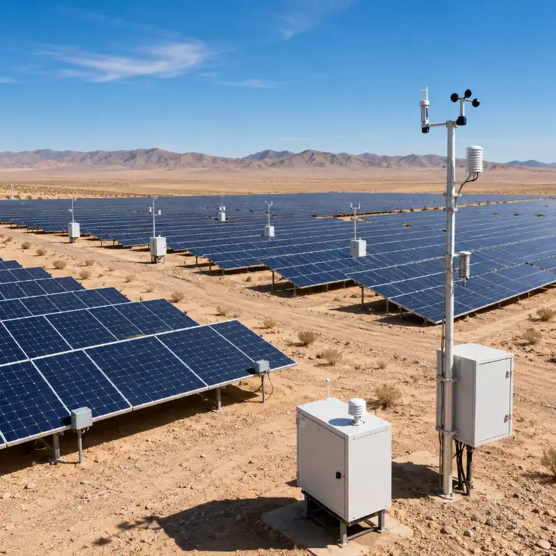
Monitoring Desert and High-Temperature PV Plants
Desert solar farms can receive abundant sunlight, but they also operate under some of the most demanding environmental conditions.
Typical challenges include:
- Very high module temperature
- Dust and sand deposition
- Strong ultraviolet radiation
- Wind-blown particles
- Large day-night temperature variation
- Limited water for cleaning
- Remote installation locations
- Long communication distances
- Cable and enclosure aging
- Rapid sensor contamination
A reliable desert PV monitoring system should combine module temperature measurement with irradiance, ambient weather, soiling, and power-generation data.
Explore the JW-IoT Desert Solar Soiling Monitoring System for integrated dust-loss, irradiance, module temperature, and desert weather monitoring.
High Module Temperature and Low Wind Speed
Module temperature may rise rapidly when strong solar irradiance occurs together with low wind speed.
Wind can help remove heat from the front and rear surfaces of a PV module. When airflow is limited, heat accumulation may become more severe.
This is particularly relevant for:
- Low-clearance ground-mounted arrays
- Flat commercial rooftops
- Closely spaced modules
- Sheltered valleys
- Sites with structural wind barriers
- Areas with limited rear ventilation
Monitoring module temperature together with wind speed helps operators evaluate whether thermal loss is caused by site design, temporary weather conditions, or abnormal equipment behavior.
Large Day-Night Temperature Changes
Desert environments may be extremely hot during the day and considerably cooler at night.
Repeated temperature cycling can affect:
- Cable insulation
- Connectors
- Junction boxes
- Adhesives
- Sensor mounting materials
- Protective enclosures
- Communication equipment
- Module packaging materials
The temperature sensor itself should be selected for the expected operating range, not only the average daytime temperature.
The entire monitoring chain—including sensor, cable, connector, data logger, gateway, and enclosure—must be suitable for the site’s maximum and minimum temperatures.
Dust Can Affect Both Temperature and Irradiance
Dust accumulation reduces the solar radiation reaching the PV cells, but it may also change the thermal behavior of the module.
A heavily soiled module may absorb and dissipate heat differently from a clean module. Uneven soiling can also contribute to localized thermal differences.
For this reason, desert PV monitoring should compare:
- Clean reference irradiance
- Soiled reference irradiance
- Module temperature
- Ambient temperature
- Wind speed
- Power output
- Cleaning records
This makes it easier to distinguish temperature-related loss from dust-related optical loss.
A dedicated PV soiling monitoring solution can help operators quantify dust-related performance loss and optimize cleaning intervals.
Cleaning Decisions in Hot Environments
Cleaning modules during extremely hot periods can create operational and safety concerns.
A sudden change in surface temperature may place additional thermal stress on the module. Cleaning crews may also face heat exposure and reduced working efficiency.
Real-time module temperature data can support decisions about:
- Suitable cleaning times
- Early-morning or evening maintenance
- Heat-related worker safety
- Water-temperature considerations
- Robotic cleaning schedules
- Post-cleaning performance verification
The final cleaning procedure should follow the module manufacturer’s instructions and the plant’s O&M safety rules.
Monitoring in Tropical and Humid Climates
Extreme climate monitoring is not limited to deserts.
In tropical regions, PV plants may experience:
- High ambient temperature
- High relative humidity
- Frequent rain
- Condensation
- Salt mist in coastal areas
- Biological growth
- Rapid weather changes
- Strong storms
- Limited module ventilation
Module temperature sensors used in these environments should have suitable ingress protection, corrosion-resistant materials, stable cable sealing, and reliable outdoor connectors.
Humidity and rainfall data should be integrated with temperature readings because rapid cooling from rainfall can create sudden changes in module temperature.
Monitoring these patterns helps operators understand thermal cycling and distinguish normal weather-related temperature changes from sensor faults.
Monitoring in Cold and High-Altitude Regions
Cold climates can improve PV conversion efficiency when modules receive strong sunlight at low operating temperatures.
However, cold and high-altitude installations present different monitoring challenges:
- Snow cover
- Ice formation
- Frost
- Strong ultraviolet radiation
- Rapid heating after sunrise
- Large thermal gradients
- Strong wind
- Low atmospheric pressure
- Cable brittleness
A temperature sensor should remain firmly attached during freezing, thawing, snow loading, and wind vibration.
The selected adhesive and cable materials must remain suitable across the full temperature range.
In snowy climates, temperature data can also support snow-loss analysis. A module remaining near freezing while irradiance rises may indicate snow cover or incomplete exposure.
Comparing Multiple Temperature Sensors
For utility-scale PV plants, multi-point monitoring can provide more useful information than a single sensor.
Sensors may be installed on representative modules in:
- Different inverter zones
- Opposite ends of the plant
- High and low terrain
- Central and edge rows
- Wind-exposed and sheltered locations
- Clean and heavily soiled zones
- Different tracker groups
- Different module technologies
The monitoring platform can then compare temperature differences among zones.
A persistent temperature difference may indicate:
- Different airflow conditions
- Uneven soiling
- Mounting variation
- Sensor installation inconsistency
- Electrical underperformance
- Localized environmental conditions
Before treating a difference as a plant fault, operators should verify that the sensors were installed using the same method and on comparable module positions.
Data Integration with PV Weather Stations
PV module temperature becomes most useful when it is integrated with other environmental and electrical parameters.
A complete PV weather station may monitor:
- Plane-of-array irradiance
- Global horizontal irradiance
- Module backsheet temperature
- Ambient air temperature
- Relative humidity
- Wind speed
- Wind direction
- Rainfall
- Atmospheric pressure
- Optional soiling or dust loss
JW-IoT’s PV plant weather station solution supports real-time module backsheet temperature monitoring, multi-point comparison, temperature-loss analysis, and abnormal-temperature alarms.
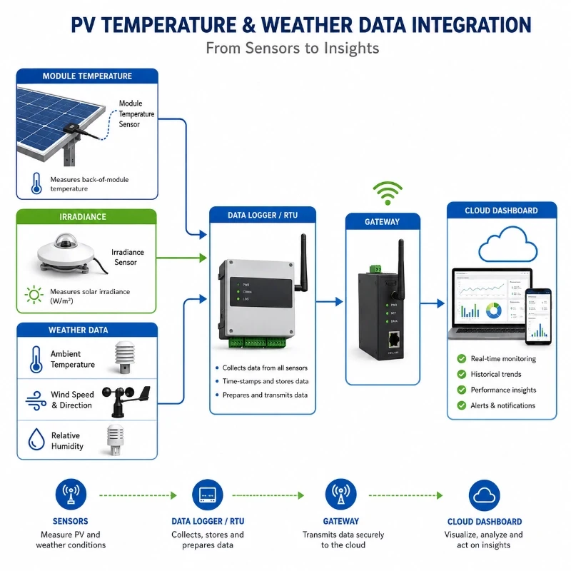
The recommended data path is:
Module temperature sensor → data logger or RTU → communication gateway → cloud or local platform → PV performance analysis
Synchronize Temperature, Irradiance, and Power Data
Temperature data should use the same time reference as irradiance and electrical output data.
If the timestamps are not synchronized, the monitoring platform may compare:
- Current module temperature
- Earlier irradiance data
- Later power-output data
This can create misleading performance conclusions, especially during rapidly changing cloud conditions.
The data acquisition system should define:
- Sampling interval
- Averaging interval
- Timestamp source
- Time zone
- Data transmission interval
- Missing-data handling
- Sensor status flags
For many operational systems, short sampling intervals are aggregated into one-minute, five-minute, or fifteen-minute values. The correct interval depends on the project objectives and monitoring standard.
Use Temperature Data in Performance Models
A monitoring platform can use module temperature data to estimate temperature-corrected output.
A simplified model may consider:
- Measured irradiance
- Module temperature
- Installed DC capacity
- Module power temperature coefficient
- Inverter efficiency
- System losses
The monitoring platform can then compare expected output with actual output.
Examples of useful analytical rules include:
High Irradiance + High Temperature + Proportional Power Reduction
The plant may be experiencing normal thermal loss.
High Irradiance + Normal Temperature + Low Power Output
Possible causes may include inverter faults, string problems, shading, curtailment, or soiling.
High Irradiance + Abnormally High Temperature in One Zone
The zone may require inspection for poor ventilation, local soiling, electrical mismatch, or abnormal module behavior.
Low Irradiance + High Module Temperature
The data may indicate stored heat after a cloud transition, sensor error, timestamp mismatch, or a local thermal issue.
Nighttime Module Temperature Significantly Above Ambient Temperature
The installation, sensor offset, nearby heat source, or data mapping should be checked.
These rules should be adapted to the plant design and validated using historical site data.
Configure Alarms Carefully
A fixed high-temperature alarm can be useful, but it may generate unnecessary alerts in hot climates.
A module temperature of 70°C may be abnormal at one site but common during peak summer conditions at another.
More effective alarms may consider:
- Absolute module temperature
- Difference from ambient temperature
- Difference from neighboring modules
- Irradiance level
- Wind speed
- Duration above the threshold
- Historical baseline
- Rate of temperature change
For example, an alarm could be triggered when one module temperature sensor remains 10°C above comparable sensors for more than a defined period under similar irradiance conditions.
This type of contextual alarm is generally more useful than a single fixed threshold.
Sensor and System Selection Recommendations
The best solar panel temperature sensor depends on the plant design, climate, communication system, accuracy requirement, and installation method.
Important selection factors include:
Measurement Range
The range should cover the lowest and highest expected module temperatures.
For extreme climates, consider:
- Maximum summer backsheet temperature
- Minimum winter temperature
- Rapid temperature changes
- Storage and transport temperature
- Safety margin beyond expected conditions
Measurement Accuracy
Higher accuracy supports better comparison among sensors and more reliable temperature-corrected performance analysis.
The complete uncertainty should include:
- Sensor accuracy
- Installation contact
- Data logger accuracy
- Cable effects
- Calibration
- Sensor drift
- Location representativeness
A high-accuracy sensor installed poorly may produce less useful data than a moderately accurate sensor installed consistently.
Response Time
A suitable response time helps the sensor follow changes caused by:
- Passing clouds
- Wind gusts
- Rainfall
- Tracker movement
- Rapid sunrise heating
- Cleaning operations
The response should be fast enough for the intended sampling interval without becoming excessively sensitive to short-term noise.
Output Signal
Common options may include:
- RS485 Modbus RTU
- PT100 or PT1000 resistance output
- 4–20 mA
- 0–5 V
- 0–10 V
- SDI-12
- LoRaWAN through an external node
RS485 Modbus is practical for many PV weather stations because multiple sensors can be connected to a data logger using a digital communication bus.
Analog or resistance outputs may be preferred where the existing SCADA or data acquisition system already supports those inputs.
Outdoor Protection
The sensor assembly should be suitable for:
- High temperature
- Ultraviolet exposure
- Rain
- Humidity
- Dust
- Sand
- Salt mist
- Freezing
- Wind vibration
Cable glands, connectors, junction boxes, and exposed mounting materials should receive the same attention as the sensing element.
Communication Distance
For compact rooftop systems, a wired RS485 connection may be sufficient.
For large desert plants, the configuration may use:
- RS485 from sensors to a local RTU
- LoRaWAN between distributed monitoring points
- 4G LTE from the gateway to the cloud
- Ethernet or fiber to the plant SCADA
- MQTT or API integration with an O&M platform
Communication architecture should be selected according to distance, network coverage, power supply, data volume, and cybersecurity requirements.
Recommended Configurations by Project Type
Commercial Rooftop PV System
A practical configuration may include:
- One plane-of-array irradiance sensor
- One or two module temperature sensors
- Ambient temperature and humidity sensor
- Compact data logger
- Ethernet or 4G communication
- Cloud monitoring platform
Two module sensors may be useful when the rooftop includes different orientations or ventilation conditions.
Desert Ground-Mounted PV Plant
A recommended configuration may include:
- Thermopile pyranometer for reference irradiance
- Multiple plane-of-array irradiance sensors
- Multiple module temperature sensors
- Ambient temperature and humidity
- Wind speed and direction
- Soiling monitoring system
- Rainfall sensor where relevant
- Industrial RTU or data logger
- LoRaWAN, 4G, Ethernet, or fiber communication
- Central monitoring and alarm platform
Single-Axis Tracker Plant
The system may include:
- Irradiance sensor mounted in the tracker plane
- Module temperature sensors on representative tracker rows
- Tracker-position data
- Ambient temperature
- Wind monitoring
- Multi-zone data comparison
Cables and sensor mounts must not interfere with tracker movement.
Bifacial PV Plant
A bifacial monitoring configuration may include:
- Front-side irradiance
- Rear-side irradiance
- Front or backsheet module temperature
- Ambient temperature
- Albedo monitoring
- Soiling monitoring
- Wind data
- Representative sensors across different row positions
Rear-side irradiance, airflow, ground reflectance, and mounting height may all influence thermal and electrical behavior.
Recommended JW-IoT Monitoring Configuration
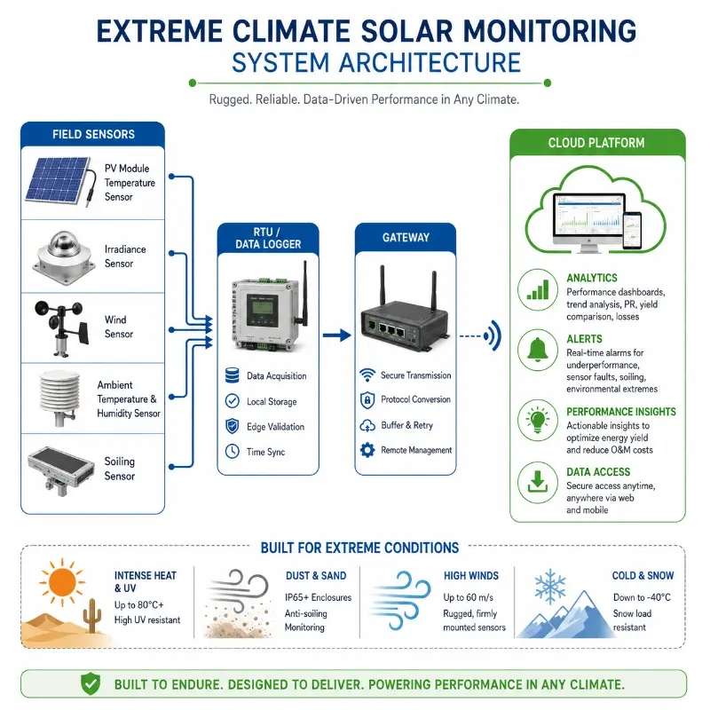
For an extreme-climate PV project, JW-IoT can configure a monitoring system with:
- PV module temperature sensors
- Solar irradiance sensors
- Ambient temperature and humidity sensors
- Wind speed and wind direction sensors
- Rain gauges
- Atmospheric pressure sensors
- PV soiling monitoring equipment
- RS485 data loggers or RTUs
- LoRaWAN communication nodes
- 4G or Ethernet gateways
- Cloud dashboards
- API or third-party platform integration
Learn more about the JW-IoT PV Module Temperature Sensor.
For sites requiring full environmental monitoring, the temperature sensors can also be integrated into a PV Plant Weather Station Solution.
Maintenance and Data-Quality Checks
Temperature sensors should be included in the plant’s routine monitoring-equipment inspection plan.
Recommended checks include:
- Verify that the sensor remains attached firmly
- Inspect cable ties and routing
- Check connectors for corrosion or water ingress
- Confirm sensor identification
- Compare nearby sensors under similar conditions
- Review nighttime readings
- Check for sudden offsets
- Inspect for frozen or repeated values
- Verify data logger scaling
- Confirm timestamps
- Recalibrate or replace sensors according to project requirements
Possible data-quality problems include:
- Sensor detachment
- Poor thermal contact
- Sensor measuring air instead of module temperature
- Incorrect Modbus register mapping
- Wrong temperature unit
- Damaged cable
- Moisture inside a connector
- Incorrect calibration coefficient
- Duplicate device address
- Communication interruption
A detached sensor may still report realistic-looking temperatures, but the values may represent ambient or enclosed air rather than the module backsheet.
Automated comparison between module and ambient temperature can help identify this problem.
Frequently Asked Questions
What is PV module temperature monitoring?
PV module temperature monitoring measures the operating temperature of a photovoltaic module, usually at the rear backsheet. The data helps operators evaluate thermal losses, improve performance analysis, and identify abnormal heating.
Why is a module temperature sensor needed if ambient temperature is already measured?
Module temperature can be significantly higher than ambient air temperature during strong sunlight. Ambient temperature alone does not accurately represent the thermal condition of the PV cells or backsheet.
Where should a solar panel temperature sensor be installed?
It is commonly attached to the rear surface of a representative module, away from the junction box, frame edges, and unusual shading. The sensing element should maintain stable thermal contact with the backsheet.
How many module temperature sensors does a PV plant need?
The required number depends on plant size, terrain, module orientation, tracker configuration, module technology, and environmental variation. Large or complex plants usually require multiple representative sensors.
What temperature can PV modules reach in desert climates?
The actual temperature depends on irradiance, ambient temperature, wind, ventilation, module design, and mounting configuration. Module temperatures can rise substantially above ambient air temperature during strong sunlight, so the sensor range should include an adequate safety margin.
Can high module temperature reduce PV power output?
Yes. Most conventional PV modules have a negative power temperature coefficient. As cell temperature rises above the reference condition, maximum power output generally decreases.
Can module temperature monitoring detect hot spots?
Continuous surface-temperature monitoring can indicate abnormal thermal patterns, especially when comparing multiple zones. However, it does not replace infrared thermography or detailed electrical inspection for individual-cell hot-spot diagnosis.
Should the sensor be installed on the front or rear of the module?
Module temperature sensors are usually installed on the rear backsheet because this avoids shading the solar cells and provides practical thermal contact with the module.
Can module temperature data be integrated with a PV weather station?
Yes. It can be collected together with irradiance, ambient temperature, humidity, wind, rainfall, and soiling data through a data logger, RTU, gateway, SCADA system, or cloud platform.
Does JW-IoT support RS485 and wireless communication?
JW-IoT can configure PV monitoring systems using RS485 Modbus, LoRaWAN, 4G LTE, Ethernet, MQTT, and selected API or platform-integration methods according to project requirements.
Conclusion
PV module temperature monitoring is essential for solar plants operating in desert, tropical, high-altitude, and other extreme climates.
High irradiance can increase potential solar generation, but it can also raise module temperature and reduce conversion efficiency. Without direct module-temperature data, operators may misinterpret thermal losses as soiling, degradation, inverter failure, or inaccurate irradiance measurement.
Reliable monitoring depends on more than choosing a temperature sensor.
The sensor must be:
- Installed on a representative module
- Attached firmly to the backsheet
- Protected from excessive ambient-air influence
- Positioned away from the junction box and frame
- Connected through reliable outdoor cabling
- Integrated with synchronized irradiance and power data
- Inspected regularly for detachment and drift
For extreme-climate projects, the most effective approach is to combine module temperature monitoring with irradiance, ambient weather, wind, soiling, and electrical data.
This integrated data helps PV operators evaluate performance more accurately, improve alarm strategies, optimize cleaning and maintenance, and identify abnormal thermal conditions earlier.
Request a PV Module Temperature Monitoring Configuration
Send JW-IoT the following project information:
- PV plant location
- Plant capacity
- Climate and expected temperature range
- Fixed-tilt or tracking structure
- Module type
- Number of monitoring zones
- Required output signal
- Communication method
- Existing data logger or SCADA platform
- Required weather parameters
- Soiling monitoring requirements
- Power-supply conditions
JW-IoT can recommend a suitable combination of module temperature sensors, irradiance sensors, weather monitoring equipment, data loggers, gateways, and cloud-platform functions.