+86 13520127780
  info@jingelway.com








Hydrostatic Water Level Measurement: 7 Factors That Can Affect Accuracy in Real Projects
Release time: 2026-08-24
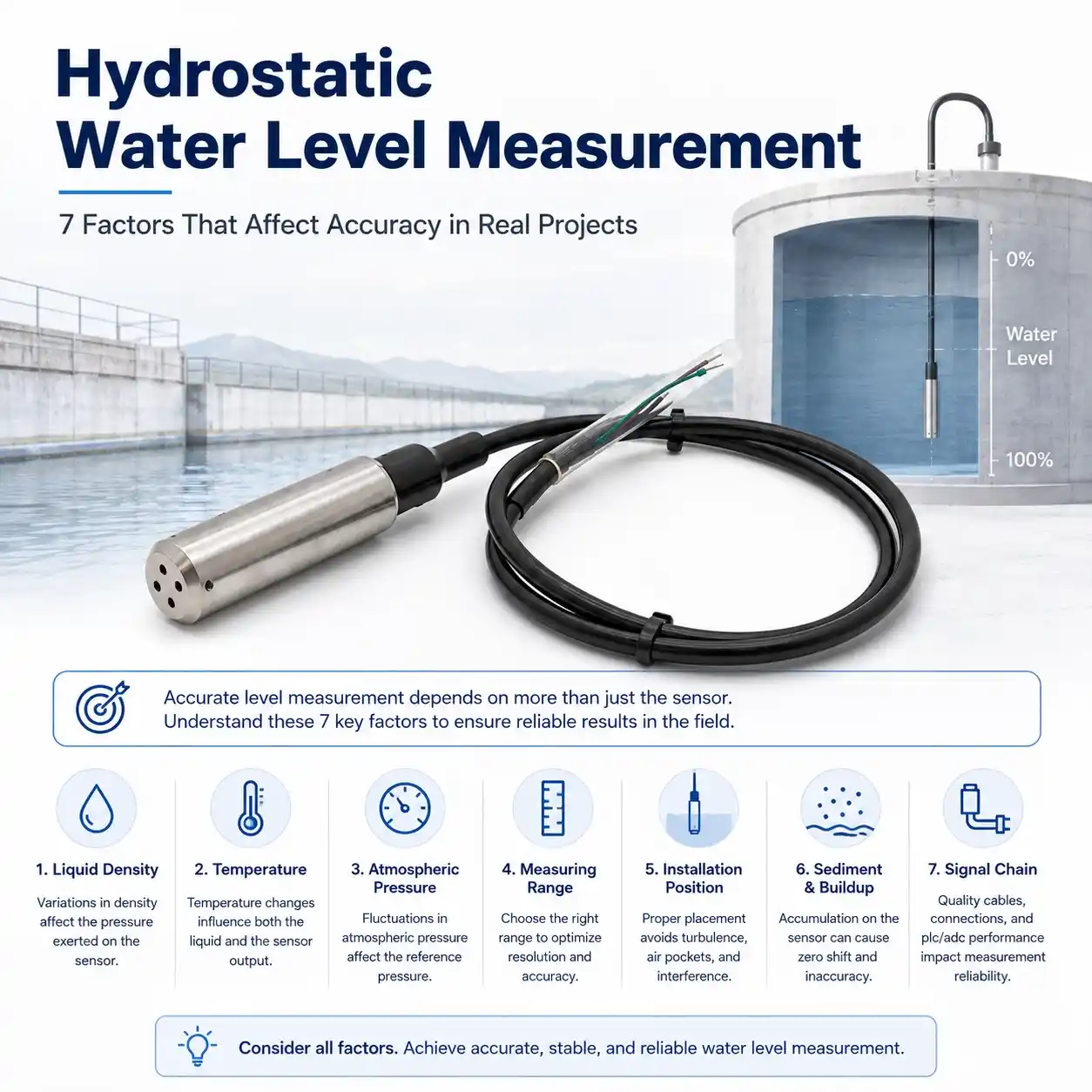
Hydrostatic water level measurement looks simple in theory.
A submerged pressure sensor measures the pressure generated by the liquid column above it, and the monitoring system converts that pressure into water level.
But in a real reservoir, groundwater well, storage tank or wastewater station, the measurement result depends on more than the pressure sensor itself.
Liquid density, temperature, atmospheric pressure, measuring range, installation position, sediment and even the data-acquisition system can influence the final level value.
That means a technically good submersible level transmitter can still produce poor field data if the complete measurement chain is not designed correctly.
This article explains seven factors engineers and system integrators should evaluate when designing a hydrostatic water level monitoring system.
1. Liquid Density Is Part of the Level Calculation
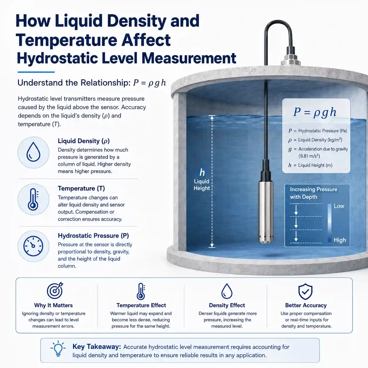
Hydrostatic level measurement is based on the relationship between pressure and the height of the liquid column.
For a static liquid:
h = P / ρg
where:
- h = liquid height
- P = hydrostatic pressure
- ρ = liquid density
- g = gravitational acceleration
This equation reveals one of the most important facts about hydrostatic measurement:
The sensor measures pressure directly, not water height directly.
Water level is calculated from the measured pressure using an assumed or known liquid density.
For many clean-water applications, density remains sufficiently stable for straightforward level monitoring.
However, applications can become more complicated when the medium changes.
Examples include:
- wastewater with changing suspended-solids concentration
- brine or saline water
- process liquids with changing composition
- liquids exposed to large temperature variations
- sludge or mixed industrial liquids
If the actual density differs significantly from the value used by the monitoring system, the calculated level can also differ from the real liquid height.
Practical Question
Before specifying a hydrostatic transmitter, ask:
Is the liquid density reasonably stable during normal operation?
If the answer is no, the project may require density compensation, additional process measurements or a different level measurement technology.
JW-IoT provides a range of water level, flow and other water monitoring sensors for different field conditions.
2. Water Temperature Can Affect More Than the Sensor
Temperature is often discussed only as a sensor specification.
In hydrostatic level measurement, however, temperature can affect the system in two different ways.
Sensor Temperature Drift
Piezoresistive pressure sensing elements can be affected by temperature.
Changes in temperature can influence:
- zero output
- span
- sensitivity
- electronic signal characteristics
This is why pressure transmitters commonly use calibration and temperature-compensation techniques.
For applications with large seasonal or process-temperature changes, the transmitter’s operating and compensated temperature range should be checked against the expected site conditions.
Liquid Density Changes
Temperature also changes the physical density of the liquid.
As water temperature changes, the relationship between pressure and water-column height changes slightly.
In many ordinary water-storage applications this effect may be small enough that no additional correction is required.
But the effect becomes more relevant when:
- high measurement accuracy is required
- the liquid temperature varies substantially
- long-term trend analysis is important
- hydraulic gradients between monitoring wells are being compared
- the medium has a larger temperature-dependent density change than water
Therefore, temperature should be considered both as a sensor performance factor and a liquid-property factor.
3. Atmospheric Pressure Compensation Matters in Open Water Systems
Reservoirs, groundwater wells and open tanks are exposed to the atmosphere.
The pressure measured by a submerged sensor can therefore contain two components:
Atmospheric pressure + hydrostatic water pressure
The monitoring system needs to distinguish the pressure caused by the water column from changes in atmospheric pressure.
Otherwise, changing weather conditions could appear as a false change in water level.
There are two common approaches.
Vented Gauge Measurement
A gauge-type submersible transmitter may use a vented cable that allows the sensor reference side to track atmospheric pressure.
In this arrangement, atmospheric pressure is compensated mechanically through the pressure reference.
The vent path must remain:
- open to atmosphere
- dry
- free from blockage
- protected against condensation and water ingress
A damaged or obstructed vent system can introduce measurement errors even when the sensor itself is functioning correctly.
Absolute Pressure Measurement with Barometric Compensation
Another approach uses an absolute pressure sensor.
A separate barometric pressure measurement is then used to compensate the data:
Hydrostatic pressure = absolute submerged pressure − atmospheric pressure
This method can be useful in monitoring networks where independent barometric data are already available.
Which Method Is Better?
Neither method is automatically better for every project.
The choice depends on:
- installation environment
- cable length
- moisture risk
- maintenance conditions
- network architecture
- required accuracy
The atmospheric-reference method should therefore be confirmed during project design rather than treated as a minor accessory issue.
4. Measuring Range Should Match the Real Water Column
One of the most common mistakes in sensor selection is choosing a pressure range that is much larger than the actual measurement requirement.
For example, a project with only a few metres of water depth may not benefit from selecting a transmitter designed for a dramatically larger pressure range.
Why?
Because the useful water-level variation may occupy only a small portion of the transmitter’s full measurement span.
When specifying the measuring range, consider:
- minimum water level
- normal operating level
- maximum expected level
- sensor installation elevation
- possible flood or surge level
- required measurement resolution
- safety margin
The goal is not simply to choose the largest range available.
The goal is to choose a range appropriate for the actual water column while maintaining adequate margin for abnormal operating conditions.
For project-specific applications, the JW-IoT submersible level transmitter for water, wastewater and reservoir monitoring can be evaluated according to measuring depth, liquid type, cable length and system interface requirements.
5. The Sensor Position Defines What Level You Are Actually Measuring
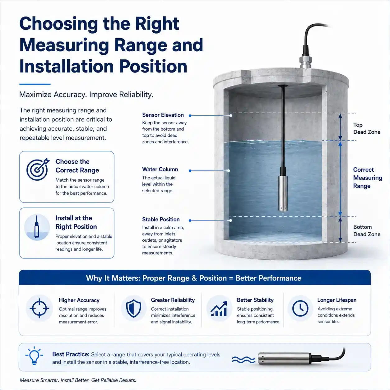
Hydrostatic transmitters measure the pressure at their physical installation point.
This sounds obvious, but it has important consequences.
Suppose a reservoir has a bottom elevation of 100.0 m and the sensor is suspended 0.5 m above the bottom.
If the system simply converts pressure into water depth without accounting for the sensor elevation, the displayed depth will not represent the total physical reservoir depth.
Therefore, engineering systems often need to distinguish between:
- water depth above the sensor
- water level relative to tank bottom
- water-surface elevation
- level relative to a project datum
These are not always the same number.
Example
A sensor measures 3.0 m of water above its diaphragm.
If the sensor is installed 0.4 m above the tank floor:
Actual depth above tank bottom = 3.4 m
If the monitoring platform needs an absolute water-surface elevation, the local installation datum must also be included.
This is particularly important in:
- reservoirs
- groundwater observation wells
- flood monitoring
- hydraulic modeling
- multi-station hydrological networks
A good commissioning record should therefore include the exact sensor reference elevation.
6. Sediment, Sludge and Turbulence Can Distort Field Measurements
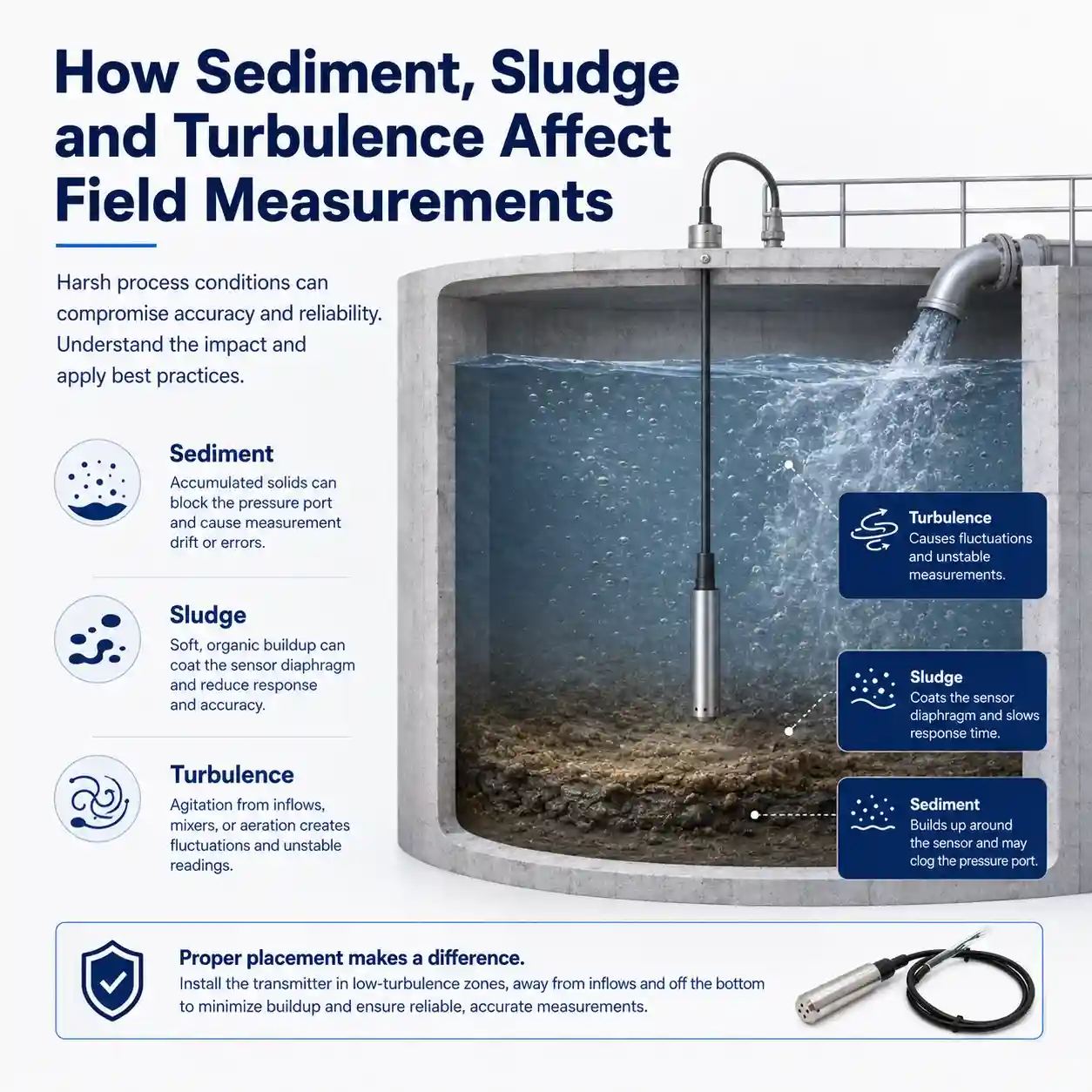
Laboratory pressure measurement takes place under controlled conditions.
Real water bodies do not.
Sediment
Reservoirs, wells and wastewater structures may accumulate sediment around the sensor.
If the probe becomes buried, the local pressure environment may no longer represent the intended free-water column.
Sediment can also complicate:
- maintenance
- retrieval
- inspection
- long-term deployment
For this reason, a submerged transmitter is often installed slightly above the expected sediment layer rather than resting directly on the bottom.
Sludge
Wastewater applications require particular attention.
High sludge concentration, grease, solids and biological buildup can make a standard clean-water installation unsuitable.
A more application-specific solution may be required.
JW-IoT lists both standard water-level transmitters and dedicated wastewater-oriented options within its water sensor portfolio.
Turbulence
Strong inflow, pumping or rapidly moving water can cause the suspended sensor to move.
This may introduce short-term fluctuations because:
- the sensor changes elevation
- dynamic pressure acts on the sensing area
- the probe may swing or strike surrounding structures
A stable installation point can therefore be just as important as the transmitter specification.
Possible engineering measures include:
- relocating the measurement point
- mechanically stabilizing the probe
- using a stilling tube or protective structure where appropriate
- applying reasonable software filtering
Filtering, however, should not be used to hide a fundamentally poor installation.
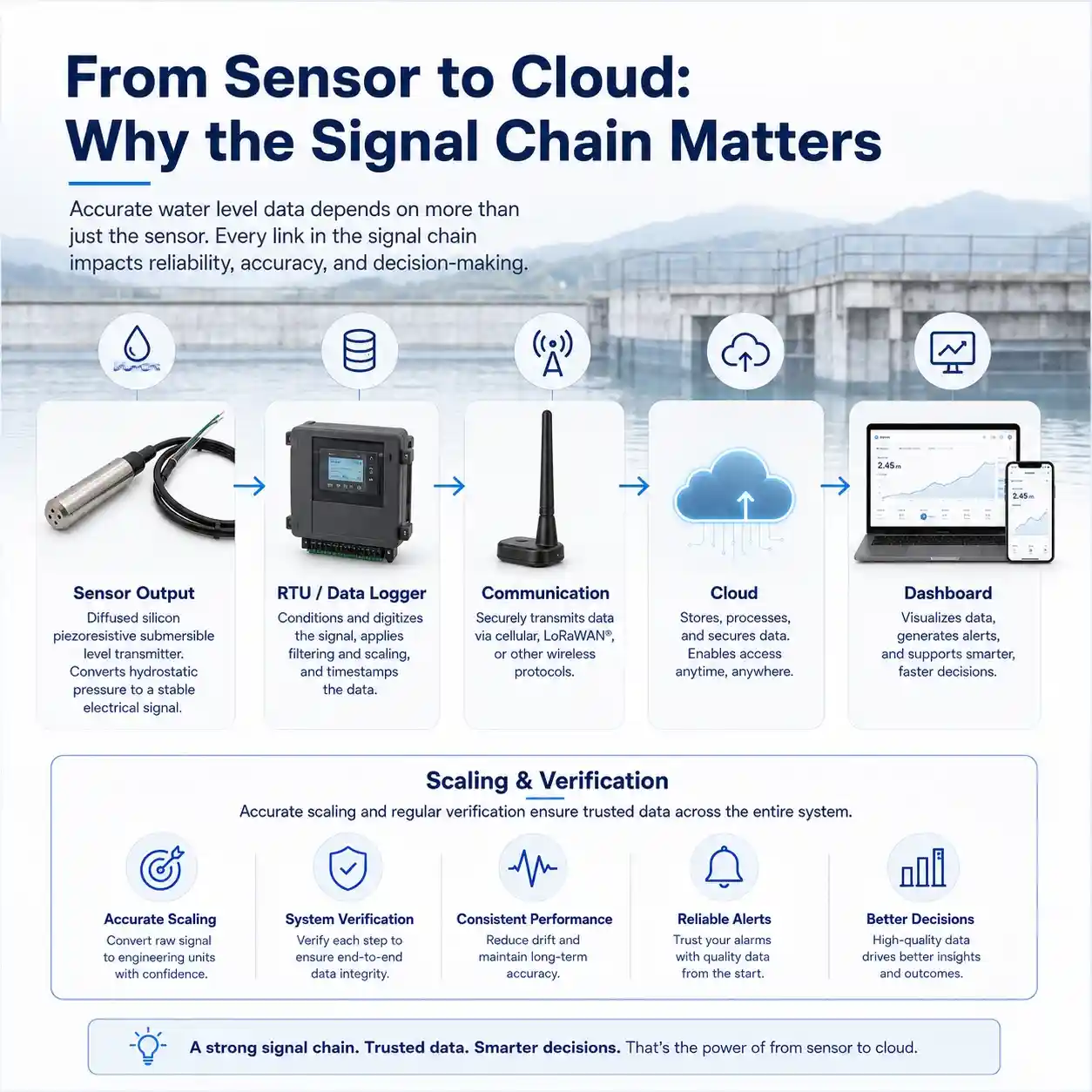
7. The Complete Signal Chain Can Affect the Final Data
A level transmitter is only the first component in a monitoring system.
A typical remote architecture may include:
Level Sensor → RTU / Data Logger → Communication Network → Cloud Platform → SCADA / Dashboard
Each stage can influence data quality.
Sensor Output
The transmitter produces the field signal.
The selected output must match the receiving device and cable distance.
RTU or Data Logger
The data-acquisition unit converts or reads the transmitter signal.
Important considerations include:
- input type
- input resolution
- scaling
- sampling interval
- grounding
- power supply stability
- surge protection
Communication
Remote monitoring projects may use:
- 4G
- LoRaWAN
- Ethernet
- other telemetry systems
Communication problems normally do not change the physical water level, but they can produce:
- missing records
- delayed data
- duplicate records
- communication alarms
- apparent gaps in trend curves
Cloud or SCADA Scaling
The final platform must correctly convert the raw electrical value into engineering units.
A simple configuration mistake can produce incorrect water-level data even when every physical device is working normally.
This is why commissioning should verify the full chain:
Known Water Level → Sensor Signal → RTU Reading → Cloud Value
not just the transmitter output.
For broader monitoring projects, JW-IoT’s Smart Water & Environmental Monitoring solutions combine water-level, water-quality and IoT monitoring components for distributed applications.
A Better Way to Commission a Hydrostatic Water Level Monitoring Point
Instead of installing the sensor and immediately accepting the first displayed value, use a structured commissioning process.
Step 1: Record the Site Reference
Record:
- sensor installation depth
- sensor elevation
- tank or well reference point
- cable length
- expected water-level range
Step 2: Compare Against a Known Level
Where practical, compare the sensor reading with an independent reference measurement.
This could be:
- staff gauge
- manual dip measurement
- surveyed water level
- known tank level
Step 3: Verify the Complete Signal Path
Compare:
- transmitter output
- RTU value
- SCADA or cloud value
The numbers should remain consistent after scaling.
Step 4: Observe the Signal Over Time
Do not judge the installation from a single reading.
Watch the trend for:
- unexpected spikes
- drift
- repeating fluctuations
- communication gaps
- unusual response during pump operation
Step 5: Document the Final Configuration
Record the final:
- measuring range
- scaling
- reference elevation
- installation depth
- platform conversion formula
- alarm thresholds
This information becomes valuable during later maintenance or sensor replacement.
When Hydrostatic Measurement May Not Be the Best Choice
Hydrostatic transmitters are useful in many water-level projects, but they are not universal.
A non-contact technology may be preferable when:
- the liquid is highly corrosive
- heavy sludge would bury the sensor
- direct contact with the medium should be avoided
- debris may damage the cable
- retrieval is difficult
- the application requires measurement from above the water surface
Radar technology is one alternative.
For example, JW-IoT’s Integrated Radar Water Level Gauge for Hydrology Stations uses non-contact FMCW radar for applications including rivers, lakes, reservoirs, canals and flood monitoring.
The decision should therefore begin with the site conditions rather than the preferred sensor type.
Hydrostatic vs Radar: A Practical Selection View
| Project Condition | Hydrostatic Submersible Sensor | Radar Level Sensor |
| Groundwater well | Often suitable | Installation may be difficult |
| Narrow borehole | Often suitable | Depends on available geometry |
| Open reservoir | Suitable | Suitable |
| Heavy debris around probe | Requires evaluation | Often advantageous |
| Direct liquid contact undesirable | Less suitable | Advantage |
| No top mounting structure | Advantage | Requires structure |
| Atmospheric compensation | Must be considered | Not normally based on liquid pressure |
| Sediment accumulation | Requires installation planning | Less direct impact |
| Very turbulent surface | Pressure measurement may remain useful if probe is stable | Application-specific evaluation required |
The purpose of this comparison is not to declare one technology superior.
It is to match the measurement principle to the physical site.
Where Piezoresistive Submersible Level Transmitters Fit
Diffused silicon piezoresistive transmitters are one implementation of hydrostatic pressure measurement.
The pressure-sensitive silicon element converts pressure-induced mechanical deformation into an electrical change that can be processed by the transmitter electronics.
This makes the technology suitable for compact pressure-based level instruments.
However, the sensing element should not be evaluated in isolation.
A reliable field transmitter also depends on:
- diaphragm design
- sealing
- temperature compensation
- housing
- cable construction
- electrical conditioning
- environmental protection
This is why two transmitters that both use “piezoresistive technology” can still have very different suitability for a particular project.
For industrial automation applications beyond water monitoring, JW-IoT also provides industrial automatic sensors covering level, pressure, temperature, flow and other measurement requirements.
Building a Multi-Parameter Water Monitoring Station
In many projects, water level alone does not provide enough information.
A monitoring site can combine level with parameters such as:
- rainfall
- flow
- water temperature
- conductivity
- turbidity
- dissolved oxygen
- pH
- ORP
For example, reservoir management may benefit from combining:
Water Level + Rainfall + Water Quality + Remote Telemetry
A wastewater station may combine:
Water Level + Flow + pH + Conductivity + Turbidity
JW-IoT’s water sensor category includes sensors for water level, flow and multiple water-quality parameters.
For applications requiring several water-quality parameters in one submerged probe, a multiparameter water quality sensor with self cleaning can also be integrated into a broader monitoring system.
FAQ
1. Does a hydrostatic level sensor measure water depth directly?
Not exactly.
The sensor measures hydrostatic pressure. Water depth is then calculated from pressure, liquid density and gravity.
2. Does atmospheric pressure affect submersible water level sensors?
It can.
Open-water applications require an appropriate atmospheric-pressure reference or compensation method so that changes in atmospheric pressure are not interpreted as water-level changes.
3. Does water temperature affect hydrostatic level measurement?
Yes.
Temperature can affect both the pressure-sensing element and the density of the liquid. The significance depends on the temperature range and required measurement accuracy.
4. Why should a submersible sensor not always be placed directly on the bottom?
Bottom sediment or sludge may bury the probe or create an unsuitable local measurement environment.
Installing the sensor above the expected sediment layer can make maintenance and measurement more reliable.
5. Can a hydrostatic level transmitter be used in groundwater wells?
Yes.
Submersible hydrostatic pressure sensors are commonly suited to groundwater wells because the compact probe can be lowered directly into the borehole.
6. Why can the cloud platform show the wrong level even when the sensor is working?
Possible causes include incorrect signal scaling, incorrect range configuration, wrong reference elevation or conversion errors between the transmitter, RTU and cloud platform.
7. When should radar be considered instead of a submersible level sensor?
Radar can be considered when non-contact measurement is preferred, when direct sensor contact is undesirable, or when debris, sediment or maintenance access makes submerged installation difficult.
Final Takeaway
Hydrostatic water level monitoring is not simply a matter of lowering a pressure sensor into the water.
Reliable field measurement depends on the complete relationship between:
Pressure + Liquid Density + Temperature + Atmospheric Reference + Installation Position + Signal Processing + System Configuration
Understanding these factors helps engineers avoid problems that may otherwise be incorrectly blamed on the level transmitter.
If you are planning a reservoir, groundwater, tank or wastewater monitoring project, start by defining the site conditions before selecting the sensor.
Explore the JW-IoT Submersible Level Transmitter for Water, Wastewater and Reservoir Monitoring or browse our complete water level and flow sensor range.
Need a project configuration?
Send JW-IoT:
- application
- liquid type
- maximum water depth
- required cable length
- monitoring points
- communication requirement
- platform or PLC interface
Our team can help evaluate the measurement and system architecture for your project.