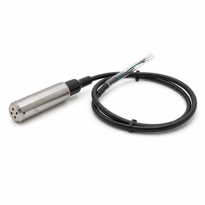
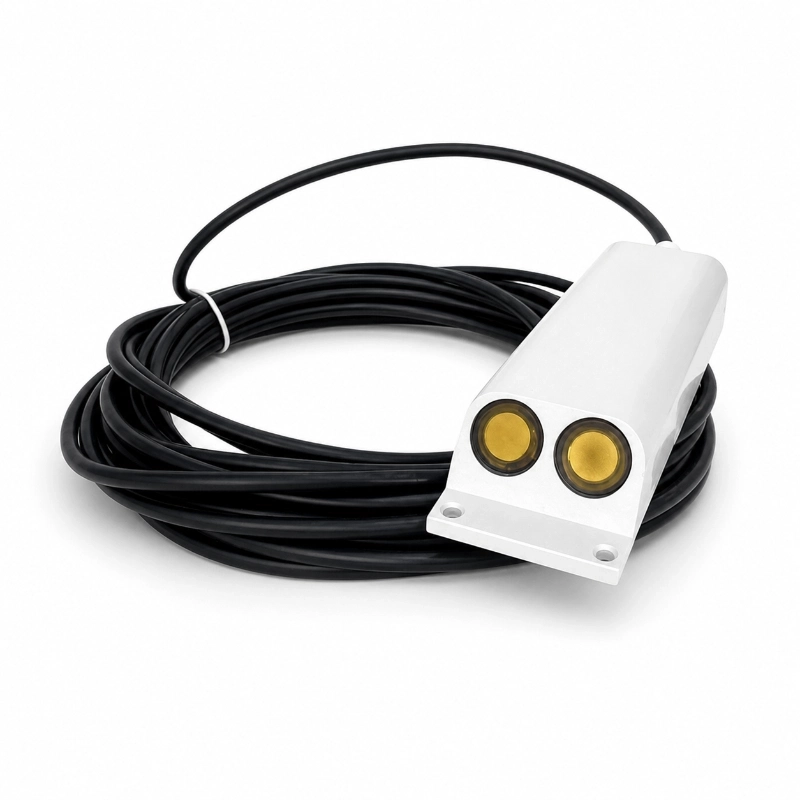
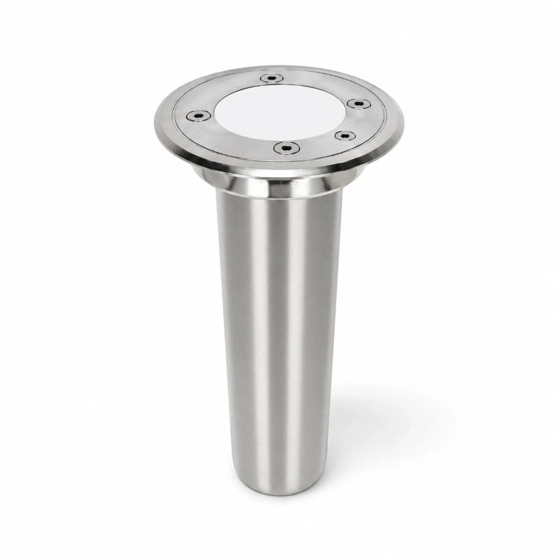
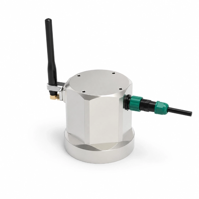
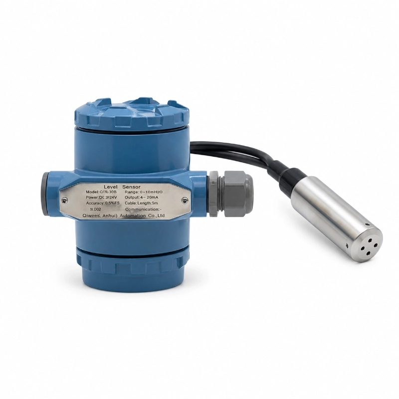
JW-LM01X(YS08) submersible level transmitter is designed for continuous liquid level measurement in reservoirs, water tanks, groundwater wells, wastewater facilities, pumping stations and other water-monitoring applications.
The transmitter uses a diffused silicon piezoresistive pressure sensing element to detect the hydrostatic pressure generated by the liquid column above the submerged sensor. The pressure signal is then converted into an electrical output that can be connected to a PLC, RTU, data logger, controller or remote monitoring system.
For water-management and industrial projects, correct selection should consider not only measuring depth, but also liquid type, cable length, output interface, installation environment and system architecture.
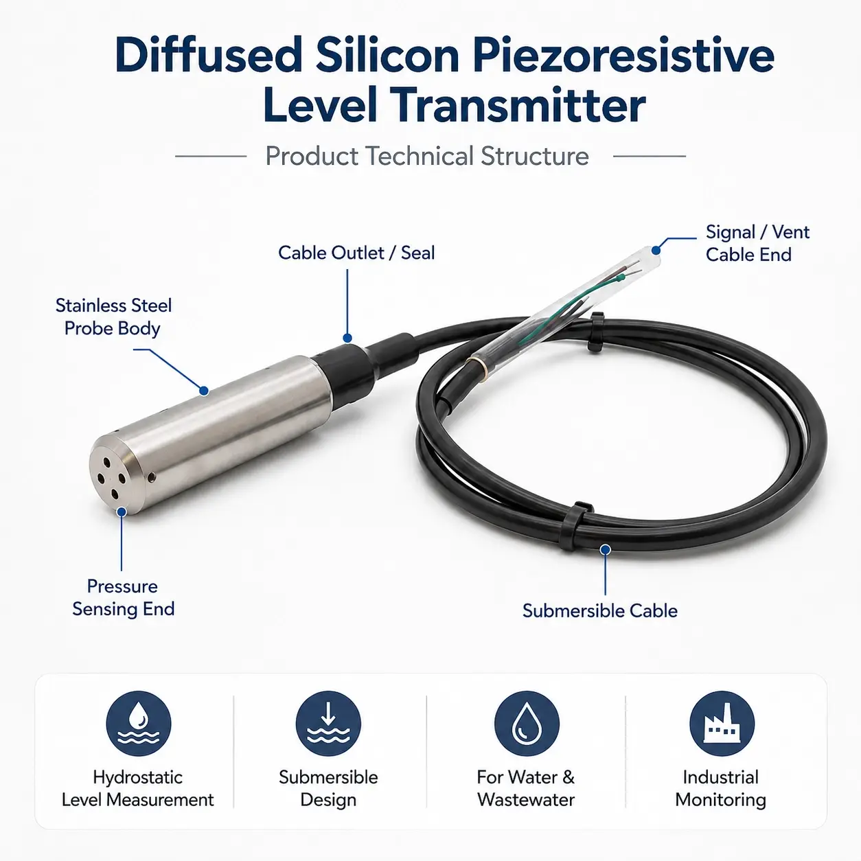
What Is a Diffused Silicon Piezoresistive Submersible Level Transmitter?
A diffused silicon piezoresistive submersible level transmitter is a pressure-based liquid level sensor that operates while submerged below the liquid surface.
Unlike radar or ultrasonic sensors that measure the distance from above the liquid, a submersible level transmitter measures the hydrostatic pressure created by the liquid column above the sensing point.
The transmitter’s pressure-sensitive element converts this pressure into an electrical signal. When the liquid level rises, the hydrostatic pressure increases. When the liquid level falls, the pressure decreases.
Because liquid height and hydrostatic pressure have a predictable relationship when liquid density is known, the measured pressure can be converted into liquid level.
How Does a Diffused Silicon Piezoresistive Level Transmitter Work?
The transmitter is lowered into the water or process liquid and installed at a defined measurement position.
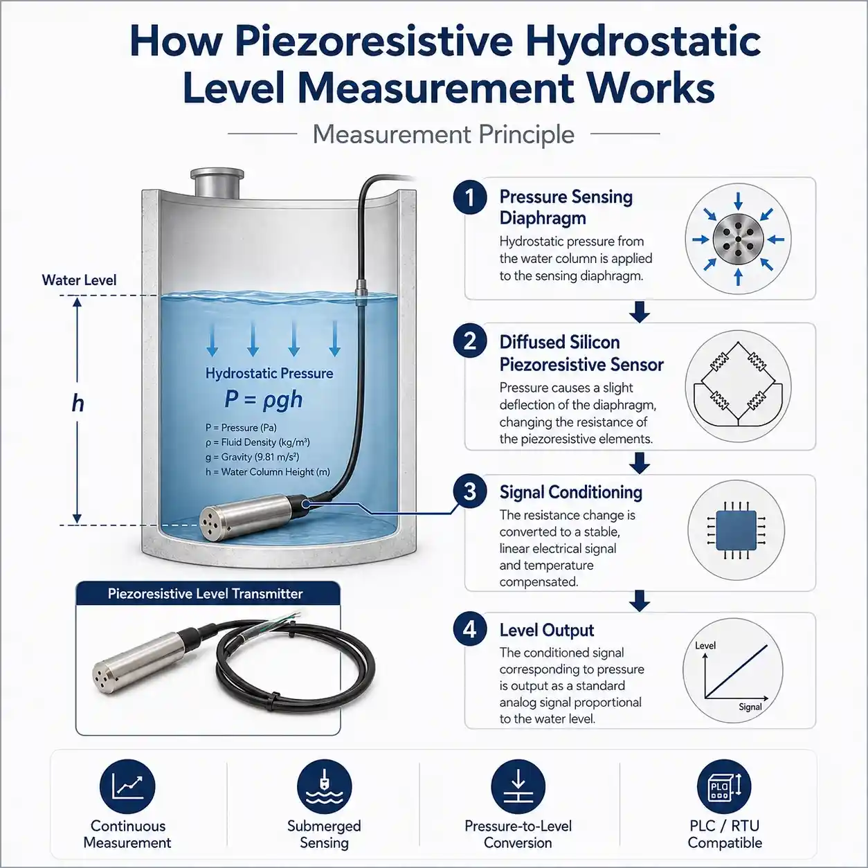
The liquid column above the sensor creates hydrostatic pressure on the sensing diaphragm.
Inside the transmitter, a diffused silicon piezoresistive sensing element responds to this applied pressure. Changes in pressure produce changes in the electrical characteristics of the piezoresistive sensing structure.
The internal signal-conditioning electronics then process this pressure signal and convert it into an output suitable for the monitoring or control system.
For a liquid with relatively stable density, hydrostatic pressure can be expressed as:
P = ρgh
where:
P = hydrostatic pressure
ρ = liquid density
g = gravitational acceleration
h = height of liquid above the transmitter
Therefore:
Higher liquid level → higher hydrostatic pressure
Lower liquid level → lower hydrostatic pressure
This is the basic principle behind hydrostatic submersible level measurement.
Why Use Diffused Silicon Piezoresistive Sensing Technology?
Diffused silicon piezoresistive technology is widely used in pressure measurement because mechanical pressure changes can be converted into measurable electrical changes.
In a submersible level transmitter, the sensing element does not directly measure “water height.” Instead, it measures pressure.
The complete measurement chain is:
Liquid Level
↓
Hydrostatic Pressure
↓
Pressure Diaphragm
↓
Diffused Silicon Piezoresistive Sensor
↓
Signal Conditioning
↓
Electrical Output
↓
PLC / RTU / Data Logger / Monitoring Platform
The performance of the complete transmitter therefore depends on more than the sensing chip alone.
Important factors include:
correct pressure range
temperature compensation
diaphragm design
housing material
cable construction
signal conditioning
sealing design
atmospheric pressure compensation
installation position
liquid compatibility
For this reason, a submersible level transmitter should be selected as a complete measurement solution rather than only by the type of sensor element inside it.
Typical Applications
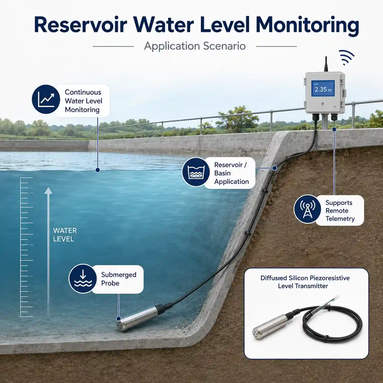
Reservoir Level Monitoring
Reservoir operators often need continuous level information for water-storage management, irrigation, pumping, supply planning and hydrological monitoring.
A submersible hydrostatic transmitter can be installed directly below the water surface and used for continuous level measurement.
Typical applications include:
municipal reservoirs
irrigation reservoirs
water-storage basins
raw-water reservoirs
balancing reservoirs
environmental monitoring sites
For remote reservoirs, the transmitter can also be connected to an RTU and wireless communication system for remote data transmission.
Groundwater and Well Monitoring
Submersible pressure transmitters are widely used for groundwater and well monitoring because the probe can be lowered directly into a borehole or observation well.
Typical applications include:
groundwater observation wells
boreholes
water-supply wells
pumping wells
aquifer monitoring
groundwater-resource projects
When selecting a transmitter for a well, the measuring range, probe dimensions and total cable length should be confirmed according to the actual installation depth.
Water Tank Level Monitoring
The transmitter can be used for continuous level measurement in open or vented water-storage tanks.
Typical applications include:
raw-water tanks
treated-water tanks
process-water tanks
irrigation tanks
fire-water tanks
utility water tanks
Continuous measurement provides more process information than a simple high-level or low-level switch and can support pump control, alarm logic and remote monitoring.
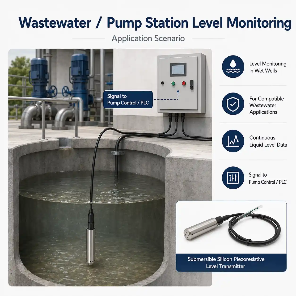
Wastewater Level Monitoring
Submersible level transmitters can also be used in compatible wastewater applications.
Typical monitoring points include:
wastewater tanks
pumping stations
lift stations
equalization basins
retention basins
settling facilities
drainage sumps
However, wastewater conditions should be evaluated carefully.
Important factors include:
solids concentration
sludge accumulation
grease
suspended particles
chemical exposure
sediment
possible sensor fouling
For applications containing heavy sludge or particularly demanding wastewater, a product specifically designed for sludge or severe wastewater environments may be more appropriate.
Is This the Right Level Sensor for Your Application?
A submersible piezoresistive hydrostatic level transmitter can be a good choice when:
continuous liquid level measurement is required
direct sensor immersion is acceptable
the application is an open tank, well or reservoir
liquid density is relatively stable
space above the liquid is limited
a narrow borehole prevents installation of larger top-mounted sensors
the level signal must be connected to a PLC, RTU or data logger
remote monitoring is required
Additional Evaluation Is Recommended When
The application contains:
high concentrations of sludge
large solids
strong corrosive chemicals
strongly varying liquid density
pressurized vessels
severe turbulence
heavy sediment
hazardous-area requirements
severe lightning or surge exposure
In these cases, the sensor configuration, diaphragm material, installation structure or even measurement technology may need to be changed.
Submersible Level Transmitter vs Radar Level Sensor
Different level technologies are suitable for different applications.
Submersible Hydrostatic Level Transmitter
Advantages
Direct continuous liquid level measurement
Compact submerged installation
Suitable for wells and boreholes
No requirement for an unobstructed measurement path above the water
Easy integration with industrial monitoring systems
Suitable for remote monitoring
Considerations
Sensor is in direct contact with the liquid
Material compatibility must be checked
Cable installation is important
Sediment and fouling should be considered
Radar Level Sensor
Advantages
Non-contact measurement
No submerged probe
Useful where sensor contact with the liquid is undesirable
Suitable for many open-water applications
Considerations
Requires suitable mounting above the liquid
Installation geometry must be considered
Obstructions in the beam path may affect measurement
Submersible Level Transmitter vs Ultrasonic Level Sensor
Ultrasonic level sensors are also commonly used for non-contact liquid level measurement.
However, the measuring principle is different.
A hydrostatic transmitter measures pressure below the water surface, while an ultrasonic sensor measures distance from above the water surface.
Hydrostatic Measurement Is Often Suitable For:
wells
boreholes
narrow tanks
submerged installations
installations without suitable top mounting structures
Ultrasonic Measurement Can Be Suitable For:
open tanks
non-contact applications
installations with a clear acoustic path above the liquid
Project conditions should be evaluated before selecting either technology.
How to Select a Submersible Level Transmitter
1. Confirm the Maximum Measuring Depth
Determine the maximum height of liquid above the sensor.
Do not select a range simply based on the total physical depth of the tank or well.
Consider:
normal water level
maximum water level
sensor mounting position
possible surge level
required usable measuring span
A measurement range that is reasonably matched to the actual application helps make better use of the transmitter’s available measurement span.
2. Confirm the Liquid Type
Tell the supplier exactly what liquid the transmitter will contact.
Examples include:
clean water
groundwater
drinking-water-related applications
municipal wastewater
industrial wastewater
seawater
process water
slurry
Do not automatically assume that a sensor suitable for clean water is suitable for every wastewater or chemical liquid.
Material compatibility should be confirmed before ordering.
3. Determine the Required Cable Length
Cable length should include the entire route from the sensor to the control or junction point.
Consider:
Sensor Position → Water Surface → Tank or Well Top → Junction Box → Control Cabinet
Allow additional length for:
suspension
routing
termination
maintenance access
Do not calculate cable length only from the liquid depth.
4. Confirm the Required Output
The transmitter must be compatible with the data-acquisition or control system.
Possible system connections may include:
PLC
RTU
data logger
industrial controller
local display
telemetry device
gateway
Use only the output option specified for the actual JW-IoT model supplied for your project.
5. Confirm the Atmospheric Pressure Compensation Method
Hydrostatic level measurement in open tanks and reservoirs normally requires the measured pressure to be referenced appropriately to atmospheric pressure.
Many submersible level transmitters use a vented cable or other atmospheric-pressure compensation design.
For the selected model, confirm:
pressure reference type
cable construction
vent protection
junction-box requirements
Do not seal or block a vented reference path unless the product installation instructions specifically allow it.
6. Review the Installation Environment
Provide details about:
indoor or outdoor installation
water temperature
ambient temperature
freezing conditions
turbulence
sediment
cable exposure
lightning risk
power availability
control system
remote communication requirements
These details are particularly important for unattended outdoor monitoring sites.
Technical Specifications
Item
Specification
Product Type
Submersible level transmitter
Standard Configuration
Fully welded insert type submersible level transmitter
The submersible level transmitter can be used as the field sensing element in a complete remote monitoring system.
A typical system may include:
submersible level transmitter
RTU or data logger
communication gateway
solar power system
cloud monitoring platform
alarm function
API or SCADA integration
This type of architecture is suitable for:
remote reservoirs
groundwater wells
irrigation systems
water-storage tanks
pumping stations
environmental monitoring networks
Typical Monitoring Architectures
Local Industrial Monitoring
Level Transmitter
↓
PLC / Controller
↓
HMI / SCADA
Suitable for:
wastewater treatment plants
factories
pumping stations
process-water systems
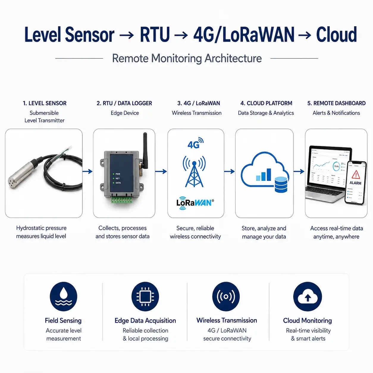
Remote IoT Monitoring
Level Transmitter
↓
RTU / Data Logger
↓
4G / LoRaWAN / Ethernet
↓
Cloud Platform
↓
Remote Dashboard / Alarm
Suitable for:
reservoirs
groundwater wells
remote tanks
irrigation sites
distributed monitoring networks
Why Hydrostatic Level Measurement Is Widely Used
Hydrostatic liquid level measurement has a straightforward physical basis: the pressure at the sensing point is related to the height and density of the liquid column above it.
This makes pressure-based level measurement particularly useful for continuous liquid level applications.
Typical advantages include:
continuous rather than point-only measurement
compact submerged installation
suitability for wells and tanks
easy connection to automation equipment
compatibility with remote monitoring architectures
no requirement for optical visibility of the water surface
However, correct measurement still depends on:
appropriate range selection
liquid density
pressure reference method
correct installation
suitable materials
proper cable handling
Common Selection and Installation Mistakes
Choosing a Measuring Range That Is Much Too Large
Selecting the largest available range is not always the best approach.
The transmitter range should be matched to the actual liquid column and project requirements.
Ignoring Liquid Density
Hydrostatic measurement depends on liquid density.
If density varies significantly, the relationship between pressure and liquid height can change.
Treating All Wastewater as the Same
Municipal wastewater, industrial wastewater and sludge can have very different characteristics.
Always consider solids, chemicals, grease and sediment before selecting the sensor.
Using an Incorrect Cable Length
The cable must reach the measurement position and the termination point.
Include routing and maintenance allowance.
Blocking the Atmospheric Reference
If the transmitter uses a vented pressure-reference cable, blocking or wetting the vent path can introduce measurement errors.
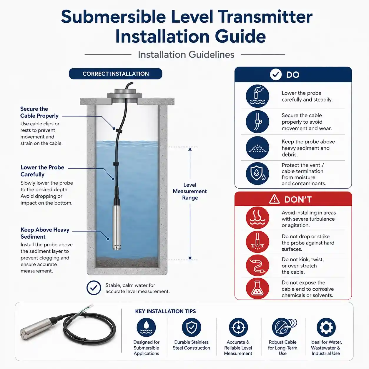
Installing the Probe Directly in Heavy Sediment
A sensor that becomes buried in sludge or sediment may no longer represent the desired water level correctly.
Installing in Strong Flow Without Stabilization
Strong flow can cause the suspended sensor to move or strike nearby structures.
Select a more stable measuring point or provide mechanical stabilization if required.
Applications by Industry
Water Resources
reservoirs
groundwater wells
water-storage structures
environmental water monitoring
Municipal Water
storage tanks
pumping stations
raw-water systems
treated-water systems
Wastewater
lift stations
wastewater basins
equalization tanks
drainage sumps
retention structures
Agriculture and Irrigation
irrigation reservoirs
agricultural wells
storage ponds
pumping systems
Industrial Water Systems
process-water tanks
utility water tanks
wastewater systems
drainage monitoring
Related JW-IoT Products
Water Sensors
Explore more water-level, water-flow and water-quality monitoring sensors:
Selecting a submersible level transmitter involves more than choosing a maximum measuring range.
For a suitable configuration, confirm:
Liquid Type + Measuring Depth + Cable Length + Output Signal + Installation Environment + Monitoring Architecture
JW-IoT can help configure the level transmitter together with RTUs, communication devices and remote monitoring components for project-based water-level monitoring.
Typical applications:
Reservoirs | Water Tanks | Groundwater Wells | Wastewater Facilities | Pumping Stations | Irrigation Systems | Environmental Monitoring
Contact JW-IoT with your project requirements for configuration and quotation.
FAQ
Q
1. What is this submersible level transmitter used for?
A
It is used for continuous liquid level measurement in water tanks, wastewater basins, deep wells, reservoirs, dams, irrigation channels and flood monitoring sites.
Q
2. What is the standard configuration?
A
The standard configuration includes a fully welded insert type structure, 0 to 1mH2O range, 4 to 20mA output, 8 to 30VDC power supply, 304SS housing and 1 meter PU cable.
Q
3. Can JW-IoT provide different measuring ranges?
A
Yes. JW-IoT can provide measuring ranges from 0 to 1mH2O up to 200mH2O according to the water depth and project requirements.
Q
4. What output signals are available?
A
Available outputs include 4 to 20mA, 0.5 to 4.5VDC, 0 to 10VDC, IIC, RS485 and SDI 12.
Q
5. Is this transmitter suitable for long-term underwater installation?
A
Yes. The transmitter has IP68 protection and is designed for submerged liquid level monitoring.
Q
6.Can JW-IoT customize the cable length and housing material?
A
Yes. JW-IoT can customize cable length, output signal, measuring range, housing material and communication interface based on the application.
Q
7. What materials are available for the diaphragm?
A
Diaphragm material options include 316L, tantalum, C276, TC4 and Al2O3 for different media compatibility requirements.
Q
8. Can this product be used for flood control and irrigation?
A
Yes. It is suitable for drainage channels, irrigation canals, reservoirs, water gates and flood control monitoring projects.
Q
9. Can JW-IoT support complete water level monitoring solutions?
A
Yes. JW-IoT can provide level transmitters, RTUs, data loggers, gateways and cloud platforms for water level monitoring and flood early warning projects.
 +86 13520127780
  info@jingelway.com