+86 13520127780
  info@jingelway.com








Mine Safety Monitoring System: Sensors, Radar, GNSS and Early Warning
Release time: 2026-07-04
Mining risks rarely develop from one parameter alone.
A slope failure may be preceded by small changes in displacement, rainfall, pore-water pressure, cracking, or blasting vibration. A tailings dam may show no obvious surface damage while internal displacement or the phreatic line is changing. An underground goaf area may settle gradually before visible cracks appear.
This is why a modern mine safety monitoring system should not depend on a single sensor.
A reliable system combines:
- Area-based deformation monitoring
- High-precision point displacement monitoring
- Hydrological monitoring
- Distributed IoT sensors
- Video and image verification
- Edge data acquisition
- Redundant communication
- Cloud-based alarm management
The purpose is not simply to collect more data. The real objective is to connect field observations with risk assessment, warning verification, and operational response.
What Is a Mine Safety Monitoring System?
A mine safety monitoring system is an integrated network of sensors, communication devices, edge gateways, software platforms, and warning mechanisms used to monitor geotechnical, hydrological, environmental, and operational risks in mining areas.
Typical parameters include:
- Surface displacement
- Internal displacement
- Slope deformation
- Crack width
- Tilt and acceleration
- Rainfall
- Reservoir water level
- Phreatic-line elevation
- Pore-water pressure
- Seepage conditions
- Blasting vibration
- Weather
- Video images
- Equipment health
The system collects these parameters continuously or at configured intervals and sends them to a centralized platform for visualization, trend analysis, alarm generation, and reporting.
A complete solution should also support local data storage, communication recovery, device-health alarms, user permissions, and multi-site management.
Why Mine Safety Monitoring Requires Multiple Sensors?
No single technology can describe the entire failure process of a slope, tailings dam, or underground structure.
For example, a camera can show whether a slope surface has changed visibly, but it may not detect millimeter-level deformation. GNSS can measure precise displacement at selected points, but it cannot automatically show deformation across an entire slope face. Radar can monitor a broad area, but it does not directly measure pore-water pressure or internal dam movement.
The strongest monitoring architecture therefore combines different types of evidence.
Area monitoring
Ground-based radar can scan a broad slope surface and identify deformation zones that may not have been selected for point-sensor installation.
Point monitoring
GNSS stations, crack meters, tilt sensors, and inclinometers provide precise measurements at critical locations.
Environmental trigger monitoring
Rainfall, water level, pore pressure, seepage, and weather data help explain why deformation is changing.
Visual verification
Cameras and UAV imagery provide operational context and help safety teams verify field conditions remotely.
Communication and system-health monitoring
The monitoring system must also determine whether data are current, whether sensors are operating correctly, and whether communication links remain available.
This multi-sensor approach helps reduce false interpretation and provides a stronger basis for engineering decisions.
Five-Layer Architecture of a Mine Safety Monitoring System
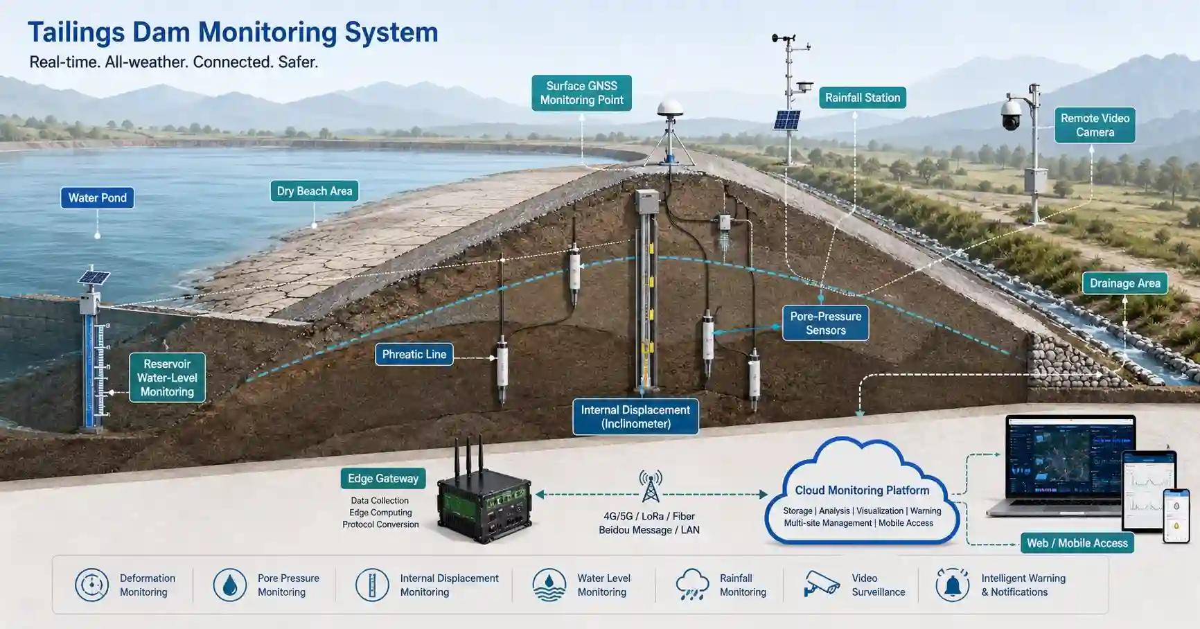
A practical mine monitoring system can be divided into five layers.
1. Perception Layer
The perception layer contains all field instruments.
Typical devices include:
- Ground-based synthetic aperture radar
- GNSS or BeiDou monitoring stations
- Crack meters
- Tilt sensors
- Slope probes
- Fixed inclinometers
- Internal displacement sensors
- Rain gauges
- Water-level sensors
- Pore-water pressure sensors
- Phreatic-line instruments
- Blasting vibration sensors
- Weather stations
- Video cameras
- UAV inspection systems
Each device measures a different aspect of risk.
2. Edge and Data-Fusion Layer
Intelligent RTUs and edge gateways collect and preprocess field data.
Typical functions include:
- Sensor polling
- Protocol conversion
- Local data storage
- Time synchronization
- Data filtering
- Device-health monitoring
- Alarm pre-processing
- Automatic retransmission
- Edge rule execution
Local storage is especially important in mines where communication may be unstable.
If the network is temporarily unavailable, the gateway should continue storing data and upload the missing records after communication is restored.
3. Communication Layer
Mining sites often have complex terrain, limited cellular coverage, and long distances between monitoring points.
The communication design may include:
- 4G or 5G
- LoRa
- LoRaWAN
- Optical fiber
- Ethernet
- Wi-Fi
- Private radio
- BeiDou short-message communication
- Satellite backup
A high-risk monitoring system should avoid relying on one communication path where failure would result in complete data loss.
The final network architecture should be selected according to:
- Terrain
- Monitoring distance
- Data volume
- Power availability
- Required update interval
- Regulatory reporting needs
- Emergency communication requirements
4. Cloud Platform Layer
The cloud platform centralizes data from sensors, video systems, and monitoring sites.
Typical functions include:
- Real-time dashboards
- GIS map display
- Trend curves
- Alarm thresholds
- Rate-of-change analysis
- Device-health monitoring
- Historical data
- User permissions
- Alarm acknowledgement
- Inspection records
- Multi-site management
- Report generation
- API integration
The platform may be deployed in a public cloud, private cloud, or local server environment, depending on the client’s cybersecurity and data-governance requirements.
5. User Application Layer
Different users require different views of the same data.
Mine operators may need real-time status and alarm acknowledgement. Geotechnical engineers may need displacement curves and spatial deformation maps. Management users may need summarized risk indicators and monthly reports. Regulators may require standardized data access and audit records.
Role-based access control helps ensure that each user receives the information relevant to their responsibilities.
Ground-Based Radar for Mine Slope Monitoring
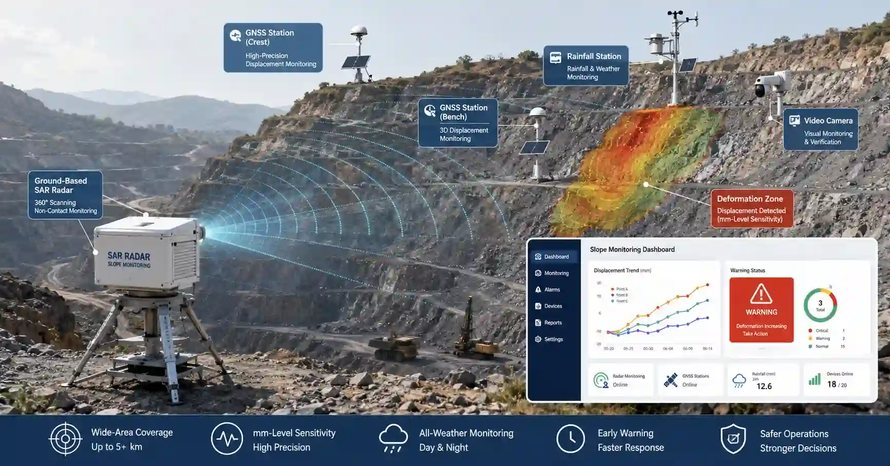
Ground-based radar is one of the most important technologies in modern open-pit mine slope monitoring.
Unlike a point sensor, radar can monitor a broad surface without installing instruments directly on every potential deformation zone.
How ground-based radar works
Ground-based synthetic aperture radar uses electromagnetic waves and phase-interferometric processing to detect small changes in the distance between the radar and the monitored slope.
The system repeatedly scans the same area. Differences between scans are processed to create deformation maps.
Radar monitoring can show:
- Deformation magnitude
- Deformation direction
- Deformation rate
- Spatial distribution
- Acceleration trends
- Areas of concentrated movement
Main advantages
Ground-based radar offers several important advantages:
- Non-contact measurement
- Broad-area coverage
- Frequent update cycles
- Remote installation
- Night-time operation
- Reduced need to enter hazardous zones
- Spatial identification of deformation zones
Important limitations
Radar is not suitable for every location without engineering assessment.
Performance depends on:
- Line of sight
- Radar position
- Slope orientation
- Surface characteristics
- Atmospheric conditions
- Installation stability
- Scan configuration
- Processing method
- Movement direction relative to the radar
For this reason, radar should be treated as part of a monitoring system rather than as a complete solution by itself.
Radar and GNSS should be used together
Radar provides area-based monitoring, while GNSS provides high-precision three-dimensional displacement at selected points.
A combined system offers both:
- Broad spatial coverage
- Precise control-point measurements
This combination is particularly useful for large open-pit slopes where it is difficult to predict exactly where deformation will begin.
GNSS and BeiDou Monitoring for Mining Deformation
GNSS monitoring stations are widely used for high-precision displacement measurement at critical points.
A GNSS station can continuously calculate changes in:
- East-west displacement
- North-south displacement
- Vertical displacement
- Total displacement
- Displacement rate
Unlike total stations, GNSS does not require direct line of sight between every monitoring point and a central observation station.
This makes GNSS suitable for:
- Open-pit slopes
- Tailings dams
- Waste dumps
- Subsidence zones
- Large deformation areas
- Remote monitoring points
However, GNSS point selection remains critical.
The monitoring station should be installed on a representative and structurally meaningful location. Poor point selection can produce accurate measurements that do not reflect the actual failure mechanism.
GNSS monuments, antenna stability, satellite visibility, power supply, and communication must all be considered during design.
IoT Slope Sensors and Distributed Monitoring
Ground-based radar and GNSS are powerful, but many projects also require dense distributed monitoring.
Low-power IoT slope sensors can measure:
- Tilt
- Acceleration
- Crack movement
- Azimuth
- Local vibration
- Surface movement
These devices are useful when monitoring points are distributed over a large area and wiring is difficult.
LoRa or LoRaWAN communication can reduce power consumption and simplify installation. Battery-powered nodes may operate for long periods depending on sampling rate, reporting frequency, environmental conditions, and battery capacity.
However, battery-life claims should always be based on actual field configuration.
The main factors affecting battery life include:
- Sampling interval
- Transmission interval
- Alarm frequency
- Signal quality
- Temperature
- Sensor power consumption
- Network retries
- Local processing
For high-risk applications, the platform should also monitor battery voltage and communication quality.
Tailings Dam Monitoring System
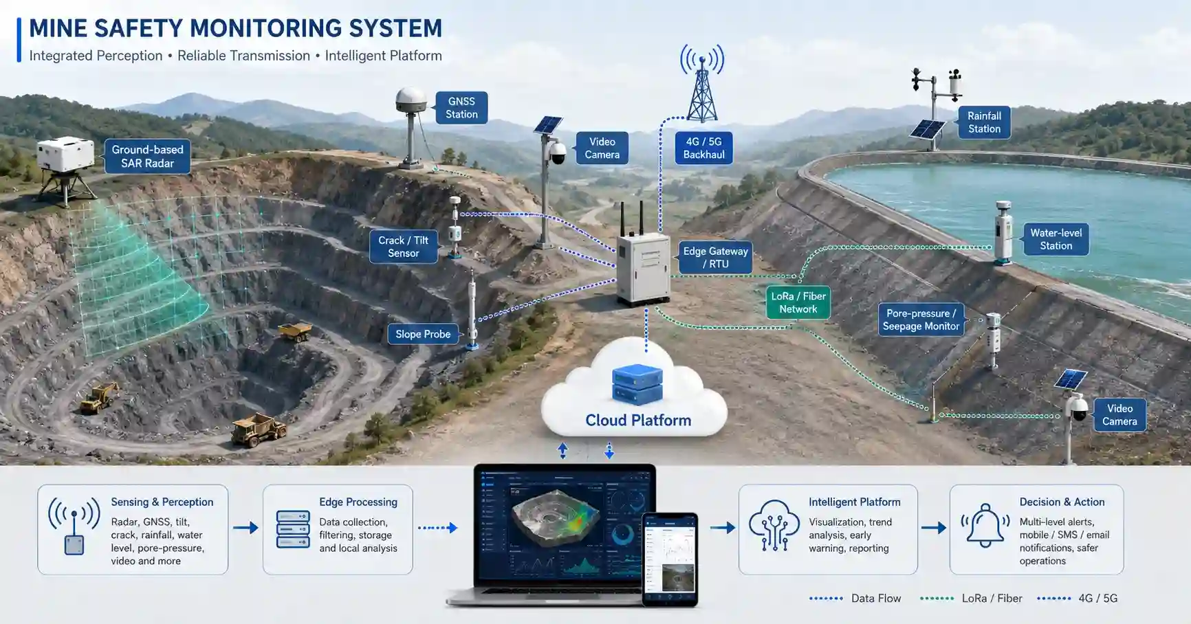
A tailings dam monitoring system must evaluate both structural deformation and water-related risk.
Surface inspection alone is not sufficient because many critical changes occur inside the dam body.
Key parameters for tailings monitoring
A complete system may monitor:
- Surface displacement
- Internal displacement
- Settlement
- Pore-water pressure
- Phreatic-line elevation
- Reservoir water level
- Rainfall
- Seepage
- Dry-beach length
- Drainage condition
- Discharge status
- Slope condition
- Video images
Why pore-water pressure matters
Pore-water pressure influences effective stress inside soil and tailings materials.
When pore pressure increases, the effective stress may decrease, reducing shear resistance and affecting slope stability.
This is why pore-pressure data should be analyzed together with:
- Rainfall
- Reservoir level
- Phreatic line
- Displacement
- Drainage performance
An isolated pore-pressure reading is less useful than a trend that is connected to rainfall and deformation.
Phreatic-line monitoring
The phreatic line represents the internal water level within the dam body.
An unexpected rise may indicate:
- Increased infiltration
- Reduced drainage capacity
- Reservoir-level influence
- Internal seepage change
- Possible hydraulic instability
Phreatic-line sensors should be installed based on the dam design and expected seepage path.
Internal displacement monitoring
Fixed inclinometers and internal displacement instruments can identify movement below the surface.
They are particularly valuable when surface movement is small but internal deformation is developing.
Visual monitoring
Video cameras can be used to observe:
- Dry-beach condition
- Drainage outlets
- Dam face
- Discharge areas
- Reservoir-bank slopes
- Restricted zones
- Water accumulation
Video should be used as supporting evidence, not as a replacement for instrumentation.
How a Mine Early-Warning System Should Work?
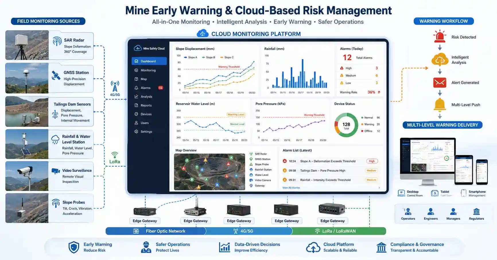
A mine early-warning system should not depend on one fixed threshold.
A more reliable system uses several levels of alarm logic.
Level 1: Device-health alarms
These alarms indicate that the monitoring system itself may not be working correctly.
Examples include:
- Sensor offline
- Low battery
- Communication failure
- Abnormal signal
- Missing data
- RTU fault
- Storage warning
Level 2: Parameter alarms
These alarms are triggered when an individual parameter exceeds an approved threshold.
Examples include:
- Displacement exceeds a limit
- Pore pressure rises above a threshold
- Rainfall intensity exceeds a configured value
- Water level reaches a warning level
- Crack width increases
- Tilt rate accelerates
Level 3: Correlated risk alarms
A correlated alarm combines multiple indicators.
For example:
- Heavy rainfall occurs
- Pore pressure rises
- Displacement rate increases
- Crack growth accelerates
Together, these signals provide stronger evidence than any one parameter alone.
Alarm escalation
A complete alarm workflow should include:
- Alarm generation
- Automatic notification
- Engineering review
- Field verification
- Response decision
- Alarm acknowledgement
- Action record
- Closure and audit
The platform should record who received the alarm, who acknowledged it, what action was taken, and when the issue was closed.
Communication Redundancy in Mine Monitoring
Communication failure is one of the most common causes of monitoring-system interruption.
Remote mines may have:
- Weak cellular signals
- Mountain or pit-wall obstruction
- Long distances
- Severe weather
- Unstable power
- Limited wired infrastructure
A resilient communication strategy should consider:
- Primary and backup links
- Local data cache
- Automatic retransmission
- Signal-strength monitoring
- Network-health alarms
- Separate video and sensor channels
- Emergency local warning
For example, low-bandwidth sensor data may use LoRa or 4G, while high-bandwidth video may use fiber or a dedicated wireless link.
BeiDou short-message communication or satellite communication may be considered as backup in remote areas where cellular coverage is unreliable.
Power Design for Remote Mining Sensors
Power design directly affects system reliability.
Possible power sources include:
- Mains power
- Solar power
- Battery power
- Portable generator
- Hybrid solar and battery systems
The power system should be selected based on:
- Sensor load
- Communication load
- Reporting frequency
- Solar radiation
- Low-temperature performance
- Required autonomy
- Maintenance interval
- Cable distance
- Lightning and surge risk
A solar-powered station should not be sized only according to average power consumption.
The design should also consider:
- Consecutive cloudy days
- Battery ageing
- Winter radiation
- Communication retries
- Heater load
- Panel contamination
- Temperature derating
Power-system health should be visible on the monitoring platform.
Data Reliability and Edge Computing
Edge computing is important in mine monitoring because field networks are not always stable.
An intelligent RTU or gateway can perform:
- Local data buffering
- Protocol conversion
- Sensor validation
- Threshold comparison
- Data compression
- Event reporting
- Communication recovery
- Device diagnostics
If communication is interrupted, data should remain stored locally.
After the network recovers, the gateway should retransmit the missing records with correct timestamps.
This prevents gaps in long-term deformation and environmental trends.
Edge devices may also trigger local warning devices when cloud communication is unavailable, depending on the project’s safety requirements.
Mine Monitoring Platform Integration
A mine safety monitoring platform should not operate as an isolated system.
It may need to exchange data with:
- SCADA
- GIS
- Mine dispatch systems
- Safety management platforms
- Government reporting platforms
- Video management systems
- Weather services
- Enterprise data platforms
Common integration interfaces include:
- Modbus RTU
- Modbus TCP
- MQTT
- HTTPS
- REST API
- WebSocket
- Database export
- CSV or Excel reports
The final integration method should be confirmed during the project-design stage.
The platform should also define:
- Data ownership
- Storage period
- Backup policy
- User permissions
- Audit logging
- API authentication
- Cybersecurity responsibilities
Mine Safety Monitoring Deployment Workflow
A successful project should begin with risk assessment rather than a product list.
Step 1: Risk zoning
Identify areas such as:
- High-risk slopes
- Tailings dam sections
- Drainage structures
- Goaf areas
- Underground deformation zones
- Waste dumps
- Reservoir-bank slopes
- Blasting areas
Step 2: Define monitoring objectives
For each area, determine whether the objective is:
- Area deformation
- Point displacement
- Internal movement
- Hydraulic change
- Vibration
- Visual verification
- Emergency warning
Step 3: Conduct a site survey
The survey should confirm:
- Terrain
- Line of sight
- Monitoring distance
- Sensor locations
- Communication coverage
- Power availability
- Installation conditions
- Environmental protection
- Cable routes
- Maintenance access
Step 4: Select sensors and communication
The device selection should match the expected failure mechanism.
For example:
- Radar for broad slope deformation
- GNSS for critical control points
- Inclinometers for internal movement
- Pore-pressure sensors for hydraulic conditions
- Rain gauges for environmental triggers
- Cameras for visual verification
Step 5: Establish baseline data
Monitoring thresholds should not be configured before the system has collected enough representative baseline data.
Baseline data help engineers understand:
- Normal movement
- Daily variation
- Temperature effects
- Blasting effects
- Rainfall response
- Seasonal change
- Sensor noise
Step 6: Test the alarm workflow
Before formal operation, the project team should test:
- Device alarms
- Parameter alarms
- SMS and email delivery
- User permissions
- Local cache
- Communication recovery
- Alarm acknowledgement
- Emergency escalation
Step 7: Maintain and optimize
A monitoring system requires ongoing maintenance.
This may include:
- Sensor calibration
- Battery replacement
- Solar-panel cleaning
- Camera inspection
- Firmware updates
- Communication testing
- Threshold review
- Alarm audit
- Data-quality review
Ground-Based Radar vs GNSS vs Total Station vs UAV
Different monitoring methods serve different purposes.
Manual patrol
Manual inspection is flexible and useful for visual checks, but it is not continuous and may expose personnel to hazardous areas.
Total station
Total stations provide accurate point measurements but require line of sight and can involve significant field workload.
UAV photogrammetry
UAVs can collect large-area imagery and terrain models, but they are affected by weather, visibility, regulation, and flight frequency.
GNSS
GNSS provides continuous, high-precision three-dimensional displacement at selected points, but it does not automatically provide full-area coverage.
Laser scanning
Laser scanning produces detailed three-dimensional data, but it is commonly used for periodic surveys rather than continuous warning.
Ground-based radar
Radar provides non-contact, frequent, area-based deformation monitoring, but requires appropriate siting, line of sight, and specialist interpretation.
The correct solution is often a combination rather than a single method.
What Information Is Needed to Design a Mine Monitoring System?
Before preparing a technical proposal, the solution provider should collect:
- Mine type
- Site layout
- Target hazard zones
- Expected failure mechanisms
- Required parameters
- Monitoring range
- Required accuracy
- Update interval
- Communication availability
- Power availability
- Weather conditions
- Data-retention requirements
- Platform integration requirements
- Alarm recipients
- Applicable standards
- Required certifications
- Installation constraints
These inputs determine the monitoring-point plan, equipment list, network architecture, platform scope, and project cost.
FAQ
1. What is the difference between mine monitoring and mine early warning?
Mine monitoring collects and displays data. Mine early warning adds threshold logic, trend analysis, alarm distribution, verification, escalation, and response records.
2. Can radar replace GNSS sensors?
No. Radar provides broad-area deformation monitoring, while GNSS provides precise three-dimensional measurements at selected points. They are complementary.
3. Can one platform monitor multiple mines?
Yes. A cloud platform can manage multiple sites, devices, users, alarms, dashboards, and reports, provided the architecture supports multi-site data isolation and role-based permissions.
4. Can the system continue operating if communication is lost?
A properly configured edge gateway can store data locally and retransmit it after communication recovery. Critical sites may also use backup communication and local warning devices.
5. How are mine warning thresholds determined?
Thresholds should be approved by qualified engineers based on design criteria, baseline data, historical trends, rate of change, operating conditions, and trigger action response plans.
6. Can third-party sensors be integrated?
Yes, provided the sensors use compatible interfaces and documented protocols such as RS485 Modbus, analog signals, pulse output, SDI-12, MQTT, or API-based communication.
7. Is the system suitable for tailings dam monitoring?
Yes. A tailings monitoring system can integrate displacement, rainfall, water level, phreatic line, pore pressure, seepage, internal movement, dry-beach monitoring, drainage, and video.
8. Does the platform use artificial intelligence?
The platform may support advanced trend analysis or validated prediction models, but many projects begin with reliable threshold rules, rate-of-change analysis, baseline comparison, and multi-parameter correlation. AI claims should only be made where the model has been validated for the specific application.
Conclusion
A modern mine safety monitoring system is not a collection of isolated sensors.
It is an integrated technical framework that connects:
- Area-based radar monitoring
- GNSS point displacement
- Distributed IoT sensors
- Hydrological instruments
- Video verification
- Edge data acquisition
- Redundant communication
- Cloud alarm management
- Engineering response procedures
The most effective system starts with the site risk model and expected failure mechanism.
Sensors, communication, power, platform functions, and alarm logic should then be selected according to actual field conditions.
JW-IoT provides modular mine monitoring architecture for open-pit slopes, tailings storage facilities, goaf areas, underground deformation, and emergency landslide observation.
Need a site-specific mine monitoring architecture?
Provide the site layout, target hazards, required parameters, communication conditions, power availability, and reporting requirements.
JW-IoT can prepare:
- Preliminary monitoring-point design
- Recommended sensor configuration
- Communication architecture
- Power-supply plan
- Cloud-platform scope
- Alarm and reporting workflow
Contact JW-IoT:
www.jw-iot.com/contact-us/