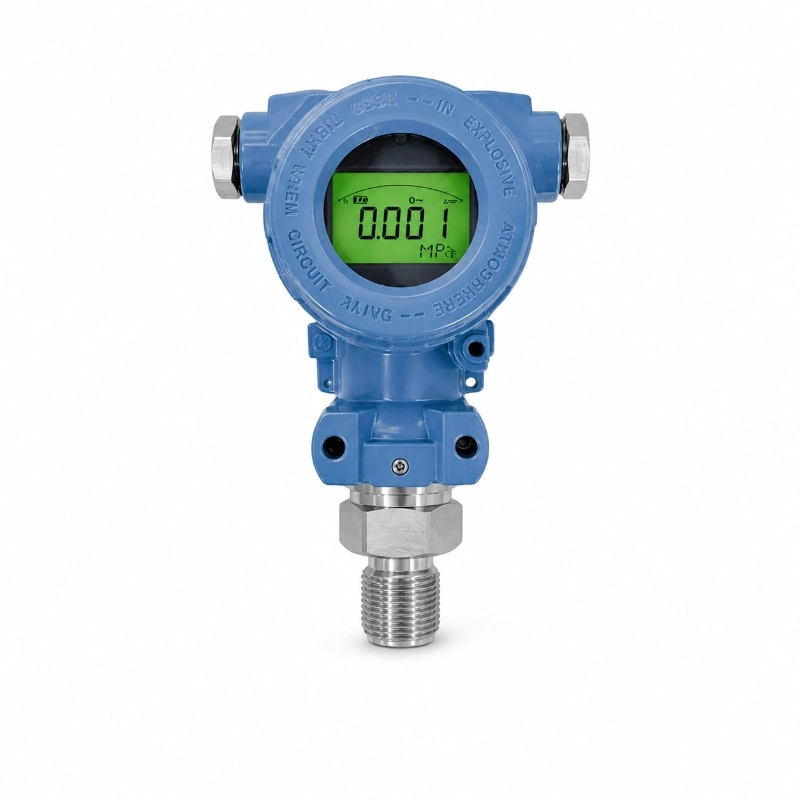
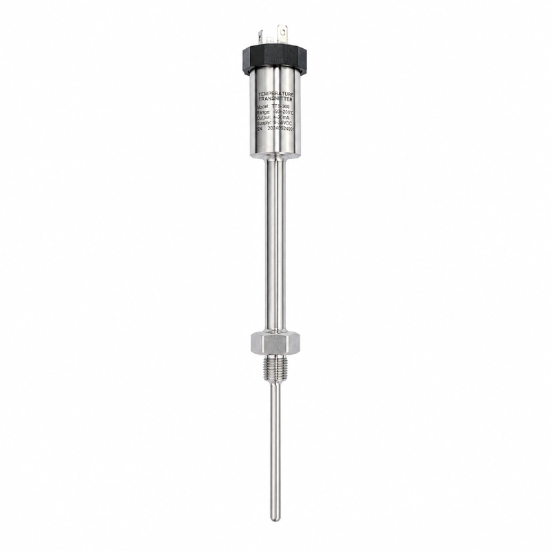
-conditioning circuitry, the transmitter supports gauge, absolute, and compound pressure measurement.
Available output configurations include 4–20mA, voltage signals, RS485, I2C, and 4–20mA with HART or RS485, depending on the selected version.
The transmitter is suitable for industrial process control, petrochemical equipment, metallurgy, electric power, hydraulic systems, and pneumatic applications.
1. How Does a Digital Display Pressure Transmitter Work?
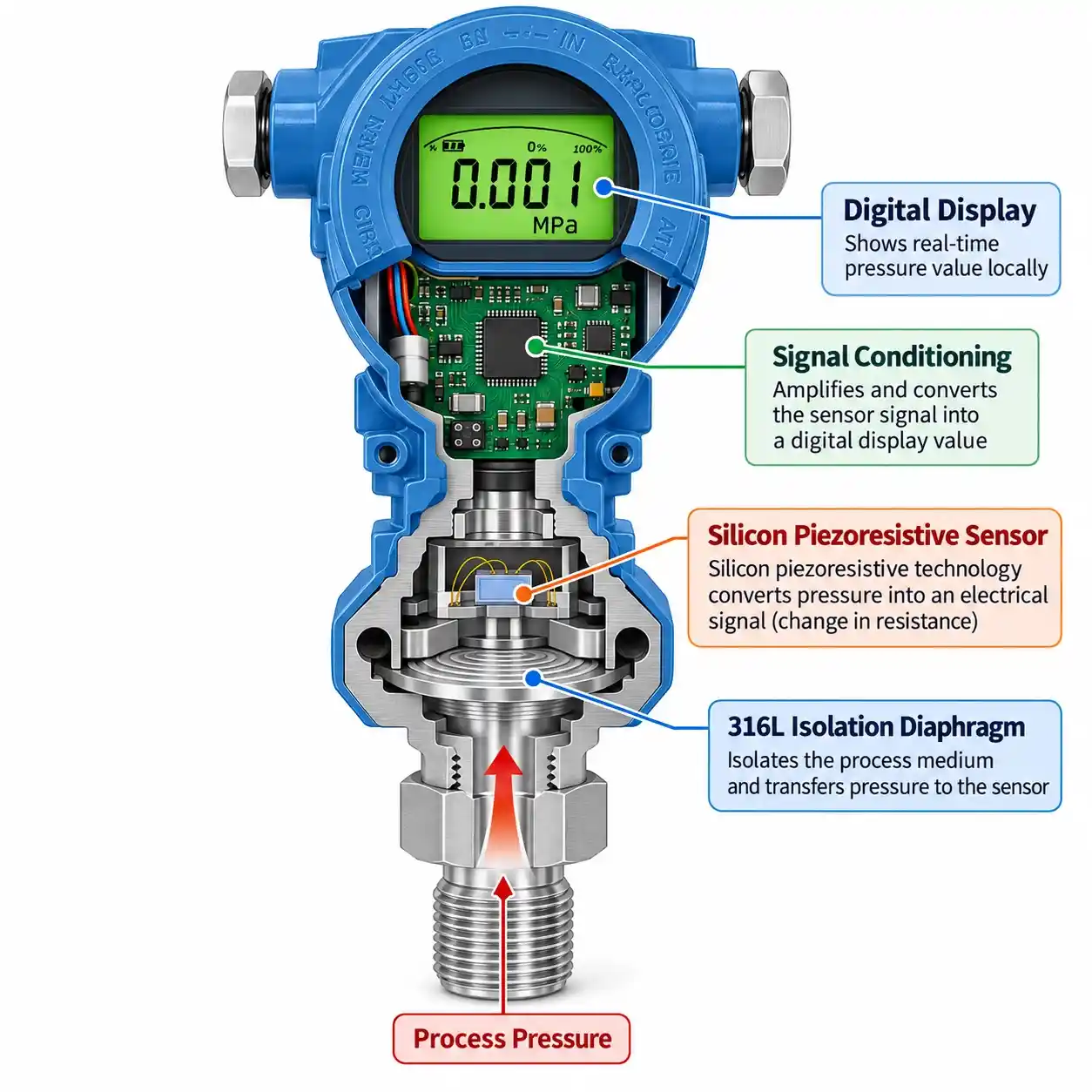
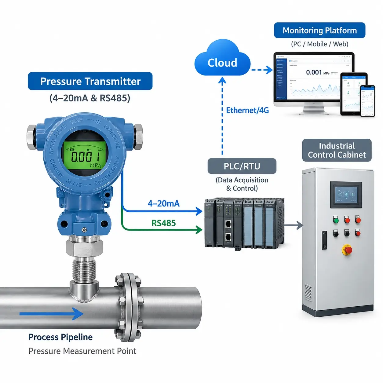
A digital pressure transmitter converts applied process pressure into a standardized electrical measurement signal.
The JW-JYB-8X(JY09) uses a silicon piezoresistive pressure sensing element isolated from the process medium by a 316L stainless steel diaphragm.
When pressure is applied, the sensor generates an electrical response corresponding to the applied pressure.
The internal digital circuitry performs signal amplification, linear compensation, and interference suppression before providing the configured output.
For display-equipped versions, operators can view pressure readings directly at the measurement location.
Why Choose a Pressure Transmitter with Digital Display?
A digital display pressure transmitter provides two important functions:
Local pressure indication for field inspection, commissioning, and troubleshooting.
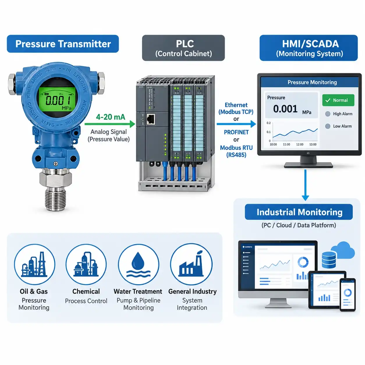
Electrical signal transmission to compatible PLCs, controllers, RTUs, or data acquisition equipment.
This makes display-equipped pressure transmitters useful in industrial installations where local inspection and remote data acquisition are both required.
2. Technical Specifications
Parameter
Specification
Product Model
JW-JYB-8X(JY09)
Sensor Principle
Silicon Piezoresistive
Isolation Diaphragm
316L Stainless Steel
Pressure Types
Gauge, Absolute, Compound
Gauge Pressure Range
0–0.05 to 0–600 bar
Absolute Pressure Range
0–0.1 to 0–25 bar
Compound Pressure Range
-1–0 to -1–25 bar
Current Output
4–20mA, 2-wire
Voltage Outputs
0–10V, 0–5V, 1–5V, 0.5–4.5V DC
Digital Options
4–20mA + HART, 4–20mA + RS485, RS485, I2C
Wiring
2-wire, 3-wire, or 4-wire configurations
Supply Options in Series Guide
8–30V DC, 5V DC, 3.3V DC
Standard Cable Material
PUR
Optional Cable Materials
PE, PTFE, PVC
Signal Processing
Amplification, Linear Compensation, Anti-interference, Surge Protection
Intrinsic Safety Reference
GB 3836.4, Ex ia IIC T6, subject to certification verification
Applications
Petrochemical, Metallurgy, Electric Power, Industrial Control, Hydraulic and Pneumatic Systems
Technical note: Available configurations depend on the selected model and output type. Confirm power supply compatibility, accuracy, process connection, and approval documentation before ordering.
3. Pressure Measurement Ranges and Overload Ratings
Different industrial applications require different pressure measuring spans.
The JYB pressure transmitter documentation provides gauge, absolute, and compound pressure ranges with corresponding overload ratings.
3.1 Gauge Pressure Ranges
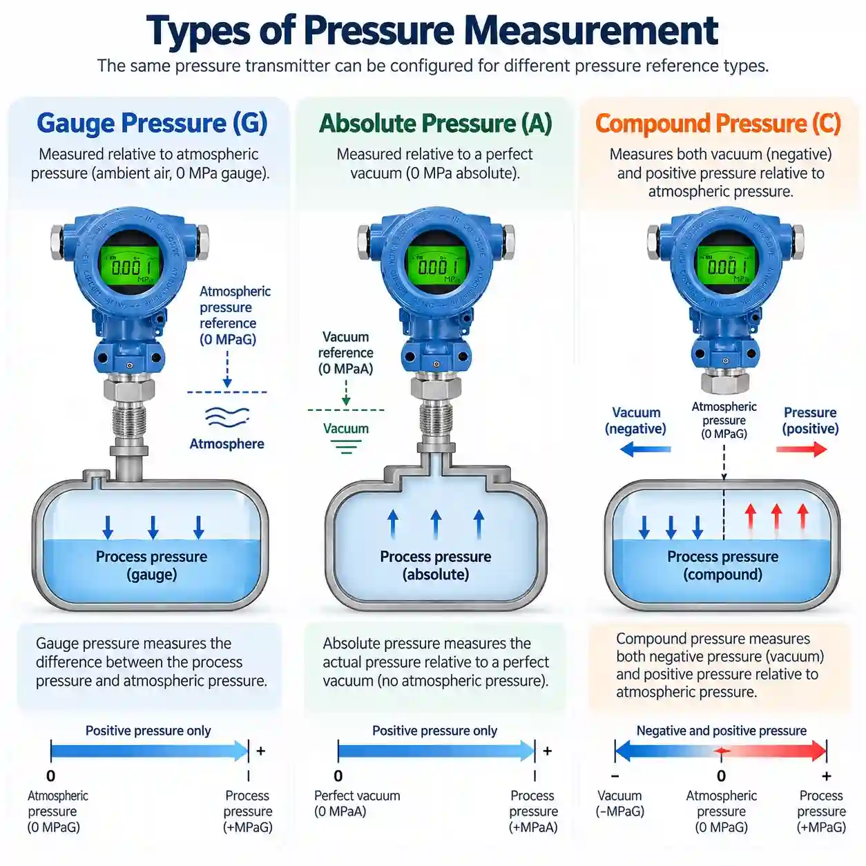
Gauge pressure is measured relative to atmospheric pressure.
Measuring Range (bar)
Overload (bar)
0–0.05
0.2
0–0.1
0.25
0–0.25
0.5
0–0.4
1
0–0.6
1.2
0–1
2
0–1.6
4
0–2.5
5
0–4
10
0–6
12
0–10
20
0–16
40
0–25
50
0–40
100
0–60
120
0–100
200
0–160
400
0–250
500
0–400
1000
0–600
1200
Gauge pressure measurement is commonly used for hydraulic equipment, compressed air networks, industrial pipelines, and pump pressure monitoring.
3.2 Absolute Pressure Ranges
Absolute pressure is referenced to a vacuum rather than ambient atmospheric pressure.
Measuring Range (bar)
Overload (bar)
0–0.1
0.25
0–0.25
0.5
0–0.4
1
0–0.6
1.2
0–1
2
0–1.6
4
0–2.5
5
0–4
10
0–6
12
0–10
20
0–16
40
0–25
50
Absolute pressure transmitters are appropriate where the measurement must be independent of changes in atmospheric pressure.
3.3 Compound Pressure Ranges
Compound pressure measurement covers vacuum and positive gauge pressure within a single measuring span.
Measuring Range (bar)
Overload (bar)
-1–0
-1.0*
-1–1
2.0
-1–1.6
4.0
-1–2.5
5.0
-1–4
10.0
-1–6
12.0
-1–10
20.0
-1–16
40.0
-1–25
50.0
4. Output Signals and Communication Interfaces
The transmitter provides multiple signal configurations for different industrial control architectures.
4.1 4–20mA Pressure Transmitter
The two-wire 4–20mA pressure transmitter configuration is suitable for industrial controllers and data acquisition systems equipped with compatible analog current inputs.
It can be used in pump monitoring, hydraulic machinery, process pipelines, and industrial automation.
4.2 Voltage Output Configurations
Three-wire voltage output options include:
0–10V DC
0–5V DC
1–5V DC
0.5–4.5V DC
These options are suitable for receiving equipment with matching voltage input ranges.
4.3 RS485 Digital Pressure Transmitter
The RS485 interface provides a digital communication option for industrial data acquisition and controller integration.
Actual protocol support, communication settings, and register information must be confirmed before connecting the transmitter to an RS485 network.
The product family documentation provides 2-wire, 3-wire, and 4-wire electrical configurations.
The terminal diagram identifies connections for output and test functions, including RS485 signal terminals where applicable.
Available power supply codes:
Code
Supply Voltage
U1
8–30V DC
U2
5V DC
U3
3.3V DC
Supply and wiring configurations are not universally interchangeable. The final electrical connection must match the selected transmitter output version.
Cable material options include standard PUR and optional PE, PTFE, and PVC.
6. Industrial Applications
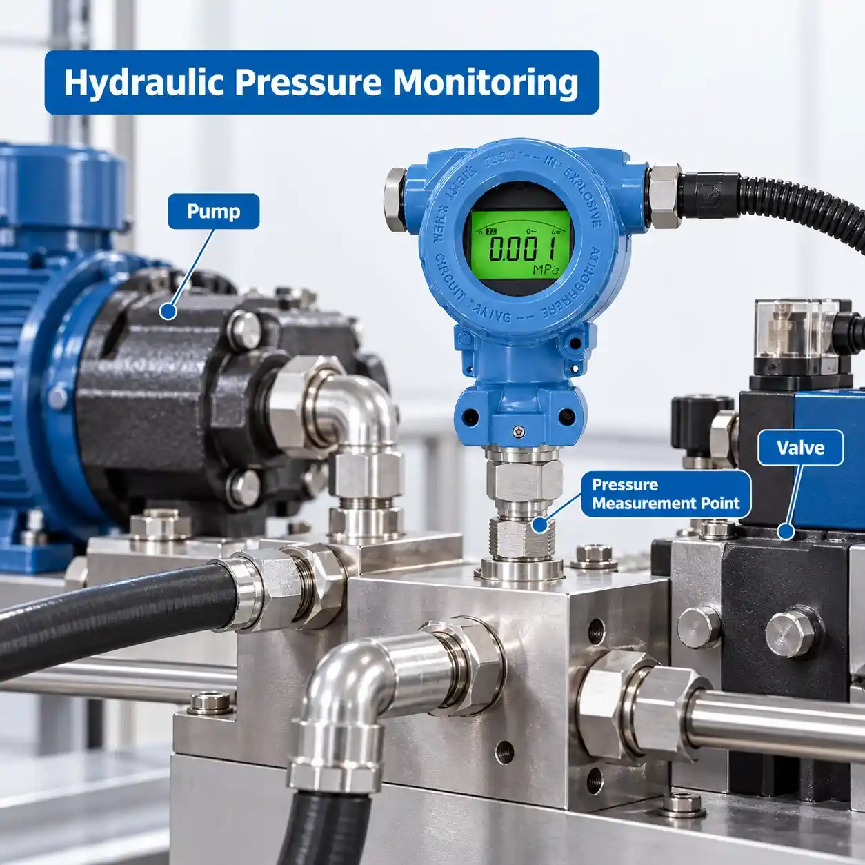
6.1 Hydraulic Pressure Monitoring
Hydraulic power units and industrial machinery require pressure feedback for equipment monitoring and control.
A digital display pressure transmitter allows local pressure inspection while transmitting measurements to connected control equipment.
6.2 Pump and Pipeline Pressure Measurement
Industrial pumps and fluid pipelines use pressure measurements to support monitoring, control, and troubleshooting.
The appropriate transmitter range should account for normal operating pressure and expected pressure variations.
6.3 Pneumatic Systems
Compressed air distribution networks and pneumatic equipment can use digital pressure transmitters for pressure measurement and automation.
The local display supports convenient field inspection at accessible measuring points.
6.4 Petrochemical and Process Industries
Pressure measurement is widely used in petrochemical production, fluid handling, and industrial process control.
The 316L stainless steel isolation diaphragm should be evaluated against the chemical properties of the measured medium.
6.5 Metallurgy and Electric Power
Metallurgical equipment and power generation facilities require pressure monitoring at suitable process and auxiliary equipment measurement points.
The transmitter’s selectable ranges and signal outputs provide options for compatible industrial instrumentation systems.
Looking for a digital display pressure transmitter with 4–20mA, RS485, or HART output for your industrial project?
JW-IoT can assist with pressure range selection, configuration review, and compatibility assessment.
Please provide the required pressure type, measurement range, process medium, output signal, power supply, process connection, and purchase quantity.
Contact JW-IoT to discuss your pressure measurement requirements.
FAQ
Q
1. What is a digital display pressure transmitter?
A
A digital display pressure transmitter measures process pressure, displays the reading locally, and provides an electrical output for remote monitoring or control.
Q
2. What pressure ranges are available?
A
The JYB series documentation lists gauge pressure ranges from 0–0.05 bar to 0–600 bar, absolute ranges from 0–0.1 bar to 0–25 bar, and multiple compound pressure ranges.
Q
3. Does the transmitter support 4–20mA output?
A
Yes. A two-wire 4–20mA configuration is listed alongside several voltage and digital output options.
Q
4. Can the transmitter connect to a PLC?
A
Yes, when the selected output signal is compatible with the PLC input module and the electrical installation requirements are met.
Q
5. Does the RS485 version support Modbus RTU?
A
The available documentation identifies RS485 as an output interface but does not confirm Modbus RTU support. Request the protocol documentation before integration.
Q
6.What is the difference between LCD and LED display versions?
A
The series selection guide identifies separate LCD and LED housing options. Their detailed display specifications should be confirmed when selecting a model.
Q
7. Are multiple power supply options available?
A
Yes. The series selection guide lists 8–30V DC, 5V DC, and 3.3V DC configurations. Availability depends on the selected output and model.
Q
8. What is the difference between measuring range and overload rating?
A
The measuring range defines the specified pressure measurement span. The overload rating indicates a separate pressure limit stated for the selected configuration; it does not extend the guaranteed measurement range.
Q
9. Can the transmitter be used in hazardous areas?
A
The original documentation references intrinsic safety requirements under GB 3836.4. Actual hazardous-area suitability must be verified using applicable certification and installation documentation.
Q
10. Can the transmitter be configured for industrial projects?
A
The JYB series documentation lists different output signals, power supply options, housing materials, and process connections. Final combinations must be confirmed for the required model.
 +86 13520127780
 info@jingelway.com