3-in 1 Integrated Radar Sensor for Open Channel Monitoring with RTU Upload
Key Features
Integrated radar velocity and level measurement: Measures surface flow velocity and water level, then calculates real-time flow rate for open channels and natural water bodies.
Non contact measurement design: No need to touch water, making it suitable for rivers with sediment, floating debris, floodwater, sewage, and corrosive environments.
FMCW radar water level technology: Uses FMCW radar level measurement to support stable water level monitoring with high precision.
Reliable surface velocity detection: Supports radar-based surface flow velocity measurement with a maximum velocity range of 40 m/s.
High measurement accuracy: Flow velocity accuracy reaches ±0.01 m/s and ±2% FS, while water level accuracy reaches ±3 mm and ±0.05% FS.
Bluetooth mobile app configuration: Built-in Bluetooth enables on-site parameter setting, debugging, and maintenance through a mobile app.
Optional integrated RTU version: The RD-600-R version supports data upload to servers or cloud platforms, reducing the need for additional telemetry devices.
Multiple communication interfaces: Supports RS485 RS232 SDI12 Modbus and optional wireless transmission including 4G NB-IoT and LoRa.
Multiple hydrology protocols supported: Supports SL651 SZY206 MQTT HJ212 HTTP and custom protocols for water conservancy and IoT platform integration.
Outdoor IP68 protection: Designed with waterproof housing, reverse polarity protection, and lightning protection for field deployment.
Low power consumption: Suitable for solar-powered monitoring stations and remote hydrological sites.
Wide application adaptability: Applicable to rivers, channels, flood control, urban drainage, ecological flow monitoring, irrigation, sewage outlets, and water resource management.
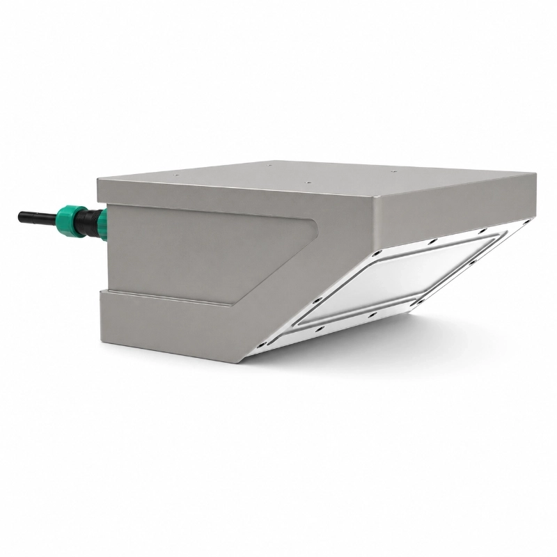
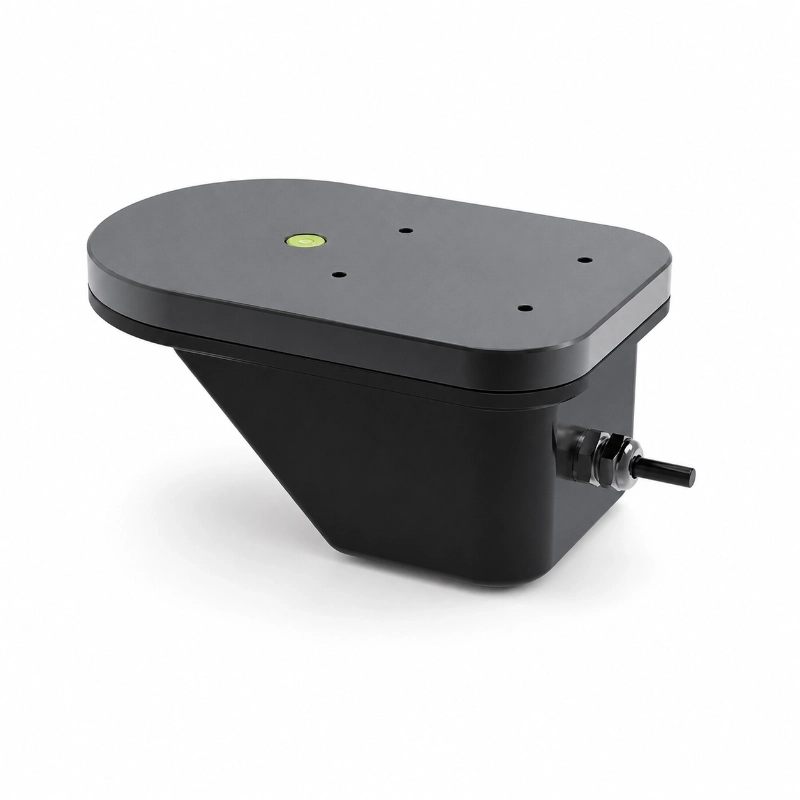
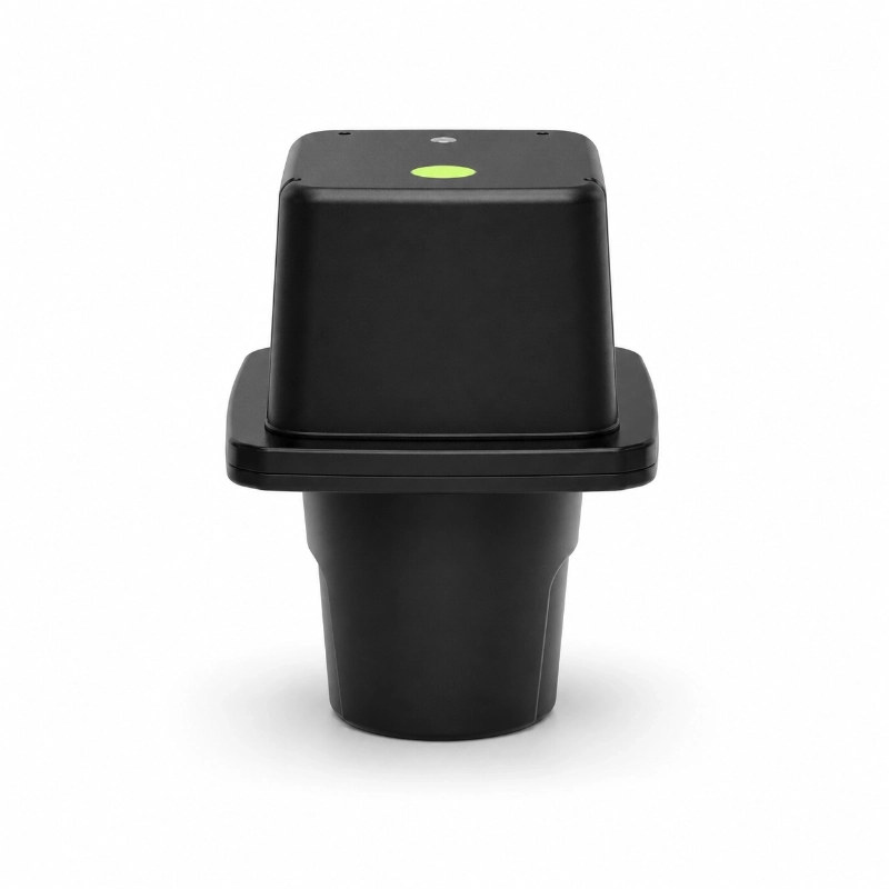
The JW-RD-600(HJ03) Integrated Radar Flow Meter is a non-contact water flow monitoring instrument designed to measure surface velocity, water level, and calculated discharge in open channels and natural watercourses.
It integrates Doppler radar velocity measurement and FMCW radar water level measurement within a single instrument. Using predefined channel geometry and hydraulic calculation parameters, the system converts measured data into instantaneous flow rate and cumulative discharge.
Unlike submerged velocity sensors, this radar flow meter operates above the water surface. It does not require direct contact with wastewater, sediment, or moving water, making it a practical monitoring option for difficult-to-access locations.
Typical applications include:
River discharge monitoring
Irrigation canal flow measurement
Urban stormwater drainage
Flood prevention and early warning
Open-channel wastewater monitoring
Water resource monitoring
Remote hydrological observation stations
The sensor can be connected to a data logger, RTU, or monitoring platform through supported communication interfaces.
The JW-RD-600 uses two radar measurement principles together with a channel-based flow calculation algorithm.
2.1 Doppler Radar Surface Velocity Measurement
The integrated velocity sensor uses 24 GHz microwave radar technology.
It transmits electromagnetic waves toward the flowing water surface. Moving surface features reflect the signals, producing a Doppler frequency shift.
The instrument processes this frequency difference to calculate water surface velocity.
The measuring process includes:
Transmitting radar waves toward the water surface.
Receiving reflected microwave signals.
Detecting the Doppler frequency shift.
Processing the signals to determine surface velocity.
Applying measurement-angle and hydraulic corrections.
The instrument provides automatic flow-direction identification and built-in vertical angle correction.
Because Doppler radar measures surface movement, it requires a suitable water surface and a stable measurement location.
Excessive turbulence, strong wind, unusual surface conditions, or insufficient radar reflection can affect measurement reliability.
2.2 FMCW Radar Water Level Measurement
The water level sensor uses Frequency-Modulated Continuous Wave (FMCW) radar technology.
The instrument transmits frequency-modulated electromagnetic waves toward the water surface and receives their reflections.
By analyzing the frequency difference between transmitted and received signals, the sensor calculates the distance to the water surface.
Water level is then determined using the configured reference height or channel-bottom elevation.
Two sensor configurations are specified:
JW-RD-600(HJ03)(A): 60 GHz radar, 0.2–7 m measuring range.
JW-RD-600(HJ03)(B): 80 GHz radar, 0.4–40 m measuring range.
The appropriate version should be selected according to the expected water level range, installation height, and monitoring environment.
2.3 Open Channel Flow Calculation
The instrument calculates flow using the velocity-area principle.
Q = A × V
Where:
Q: Volumetric flow rate (m³/s)
A: Wetted cross-sectional area (m²)
V: Average flow velocity (m/s)
The Doppler radar measures surface velocity rather than directly measuring the average velocity throughout the channel cross-section.
The instrument’s hydraulic algorithm estimates average velocity using surface velocity, channel parameters, and correction factors.
The calculated average velocity is then combined with the wetted cross-sectional area to determine instantaneous discharge.
For reliable results, users must configure the channel geometry correctly.
The instrument also provides cumulative flow values for water resource monitoring and discharge records.
Important: Calculated flow accuracy depends on site geometry, hydraulic conditions, channel parameter configuration, and installation quality. Surface velocity accuracy alone does not establish total discharge accuracy.
3. Technical Specifications
General Specifications
Parameter
Specification
Product model
JW-RD-600(HJ03)
Product versions
(A) / (B)
Measurement outputs
Surface velocity, water level, instantaneous flow, cumulative flow
Measurement principle
Planar microstrip antenna, CW + FMCW
Operating mode
Automatic / telemetry
Operating temperature
−30°C to +80°C
Operating voltage
7–30 VDC
Working current
≤28 mA at 12 VDC
Standby current
Less than 1 mA
Protection rating
IP68
Lightning protection level
6 kV
Communication
RS485 / RS232
Analog output
4–20 mA configuration; confirm availability
Wireless options
4G / LoRa, subject to configuration
Radar Velocity Measurement
Parameter
Specification
Radar frequency
24 GHz
Velocity measuring range
0.03–20 m/s
Maximum radar range (manual)
40 m
Velocity accuracy
±0.01 m/s; ±1% FS
Antenna angle
12°
Flow direction
Automatic identification
Angle correction
Built-in vertical angle correction
Radar Water Level Measurement
Parameter
Version A
Version B
Radar frequency
60 GHz
80 GHz
Measurement range
0.2–7 m
0.4–40 m
Measurement accuracy
±2 mm
±3 mm
Antenna angle
8°
8°
Dimensions
160 × 100 × 89.9 mm
235.4 × 100 × 104 mm
Weight
Less than 1 kg
Less than 1.5 kg
Specifications may depend on the selected configuration. Confirm the model version and output requirements before ordering.
4. Supported Open Channel Cross-Sections
One major advantage of the JW-RD-600 radar flow meter is its support for different channel geometries.
Unlike a water level sensor that reports only the water height, the radar flow meter uses cross-section parameters to calculate discharge.
Circular Channels
For circular conduits carrying partially filled, free-surface flow, users configure:
Channel type
Distance from the radar instrument to the channel bottom
Circular channel radius
This configuration can be relevant to suitable stormwater and drainage conduits.
Trapezoidal Channels
Trapezoidal cross-sections are common in agricultural irrigation and water conveyance projects.
Required parameters include:
Channel bottom width
Channel top width
Channel height
Distance from the instrument to the channel bottom
These parameters allow the software to calculate the wetted cross-sectional area at different water levels.
Rectangular and Triangular Channels
Rectangular and triangular geometries can be represented using appropriate trapezoidal channel parameter settings.
They may be used for engineered drainage and irrigation channels where channel dimensions are known.
U-Shaped Channels
The instrument also supports U-shaped channel configurations.
These are relevant to certain drainage and constructed water conveyance systems.
Installation recommendation: Survey the channel dimensions and confirm the actual flow conditions before configuring the instrument. Incorrect cross-section parameters can produce significant discharge calculation errors even when water level and velocity readings appear normal.
5. Communication, Modbus RTU, and Remote Data Upload
The JW-RD-600 is designed to integrate with hydrological data acquisition and remote monitoring systems.
RS485 and Modbus RTU Communication
The product supports standard Modbus RTU communication.
Setting
Default
Interface
RS485
Baud rate
9600 bps
Data bits
8
Parity
None
Stop bits
1
Communication protocol
Modbus RTU
Supported Modbus function codes include:
0x03 — Read holding registers
0x04 — Read input registers
0x06 — Write a single holding register
0x10 — Write multiple holding registers
The register list provides access to surface velocity, water level, instantaneous discharge, cumulative flow, flow direction, and diagnostic information.
Configuration registers also support channel shape, measurement parameters, serial settings, and sleep mode.
For system integration, the instrument can be connected to a compatible RTU, PLC, or data acquisition gateway.
Hydrological RTU Integration
For remote water monitoring projects, the radar flow meter can form part of a telemetry system.
A typical data path is:
Radar Flow Meter → RS485/Modbus RTU → Hydrological RTU → Communication Network → Monitoring Platform
An RTU can collect measurement data and transmit it through the communication network selected for the project.
The product documentation identifies support for the SL651 hydrological protocol in applicable RTU configurations.
Optional wireless communication includes 4G and LoRa, subject to the supplied hardware and communication setup.
For integrated telemetry versions, the exact wireless technology, SIM configuration, protocol support, and cloud connection requirements should be confirmed before deployment.
The radar flow meter supports continuous measurement and timed sleep operation.
Continuous operation offers frequent measurement updates but requires more power.
Timed sleep operation reduces power consumption by allowing the instrument to enter a low-power state between measurements.
However, the manual explains that changes in discharge during sleep intervals can create differences between calculated cumulative flow and actual flow.
For flood monitoring or applications requiring accurate cumulative discharge, long sleep intervals should therefore be avoided unless their effect on data quality is acceptable.
6. Radar Flow Meter Installation Guidelines
Correct installation is essential to reliable open-channel flow measurement.
6.1 Select a Stable Measurement Section
A suitable location should have:
A straight and stable channel section
Relatively uniform flow
A defined, measurable channel cross-section
Minimal interference from vortices or strong turbulence
Limited floating debris and aquatic vegetation
A secure support structure
Avoid sites with abrupt flow direction changes, strong backwater effects, unstable channel beds, or significant sediment accumulation.
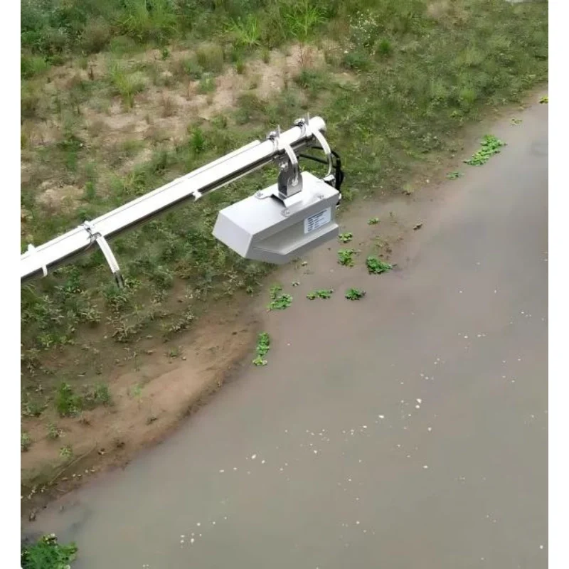
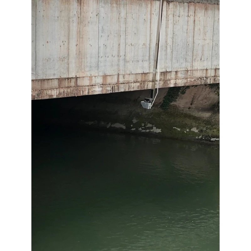
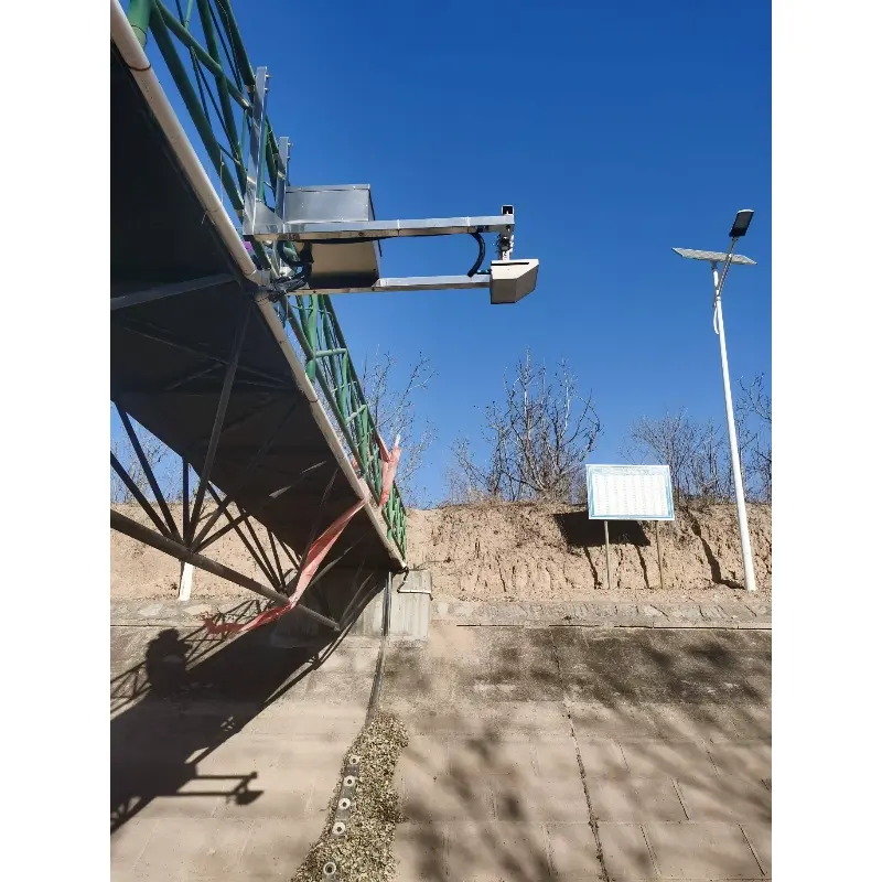
6.2 Position the Instrument Above the Water
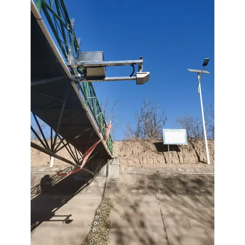
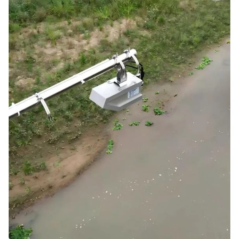
The radar flow meter is mounted above the water surface using a bracket and support structure.
The mounting arrangement described in the manual uses clamps suitable for a crossbar with a diameter of approximately 40–85 mm.
During installation:
Secure the instrument to the support bracket.
Align the instrument with the required flow measurement direction.
Adjust the instrument to the specified level position.
Ensure the radar measurement area covers the intended water surface.
Verify the installation height and channel reference parameters.
Check communication and measurement data after installation.
The radar level and velocity sensors have different beam angles.
The water level radar uses an 8° beam, while the velocity radar uses a 12° beam.
The measurement footprints therefore become larger as the installation height increases.
6.3 Avoid Unsuitable Measurement Locations
Do not select locations directly affected by:
Sharp channel bends
Large elevation drops
Strong eddies or vortices
Severe sediment deposition
Dense aquatic vegetation
Unstable gate discharge
Wind conditions that interfere with low surface velocity measurement
A stable mounting location and representative water surface are important to maintaining reliable records.
7. Typical Applications
7.1 River Flow and Hydrological Monitoring
The integrated radar flow meter can measure surface velocity, water level, and calculated discharge at river monitoring stations.
These measurements can support hydrological observation, water resource management, and river flow trend analysis.
When connected to telemetry equipment, data can be transmitted to a remote monitoring center.
7.2 Flood Prevention and Early Warning
In flood-prone rivers and channels, rising water levels and changing surface velocities provide valuable information about developing hydraulic conditions.
The sensor can be combined with rainfall gauges, RTUs, and monitoring software within a Flood Monitoring System.
Alarm rules, notifications, and emergency response functions depend on the wider monitoring system and its configuration.
7.3 Agricultural Irrigation Canal Monitoring
Irrigation canals often have defined rectangular or trapezoidal cross-sections, making them suitable candidates for velocity-area flow calculation.
A radar flow meter can support:
Canal discharge monitoring
Irrigation water distribution records
Water conveyance observation
Remote monitoring of irrigation infrastructure
7.4 Urban Drainage and Stormwater Monitoring
The sensor can be used in suitable open drainage channels, stormwater conduits, and other free-surface drainage applications.
By monitoring water level and calculated discharge, operators can better understand changing drainage conditions during rainfall events.
Non-contact radar technology is relevant to wastewater applications where direct exposure to sewage is undesirable.
Because the instrument is installed above the water, the sensing assembly does not need to be submerged in the wastewater.
However, the measurement location must still provide a suitable free surface and stable hydraulic conditions.
7.6 Remote Water Resource Monitoring
With appropriate telemetry and power components, the radar flow meter can be integrated into remote hydrological stations.
Potential applications include water resource observation, canal monitoring, river discharge monitoring, and distributed monitoring networks.
8. Non-Contact Radar Flow Meter vs Submerged Flow Sensor
Comparison
Radar Flow Meter
Submerged Flow Sensor
Sensor location
Above the water
In contact with water
Velocity measurement
Surface velocity
Depends on sensing method and placement
Water contact
No
Yes
Channel maintenance
No sensor removal from water for normal access
May require access to submerged components
Discharge calculation
Uses channel geometry and hydraulic correction
Depends on sensor type and measurement method
Key limitations
Surface conditions, mounting, hydraulic model
Fouling, sediment, submergence, or sensor-specific factors
Neither method is universally superior.
Radar measurement is particularly useful where non-contact installation is preferred, while other flow technologies may be more suitable for different hydraulic or accuracy requirements.
9. Build Your Open Channel Flow Monitoring System with JW-IoT
JW-IoT provides radar flow measurement equipment for hydrological monitoring, irrigation water management, urban drainage, and remote water resource observation.
The JW-RD-600(HJ03) combines non-contact surface velocity measurement, radar water level sensing, and channel-based discharge calculation in one instrument.
For projects requiring remote data access, the radar flow meter can be integrated with compatible RTUs, communication equipment, and monitoring platforms.
Contact JW-IoT to discuss model selection, channel geometry, communication requirements, installation conditions, and project integration.
It measures water surface velocity and water level directly, then calculates instantaneous discharge and cumulative flow using the configured channel geometry and hydraulic model.
Q
2. Does the radar flow meter contact the water?
A
No. The JW-RD-600 is installed above the water surface and uses microwave radar technology for non-contact measurement.
Q
3. What is the velocity measuring range?
A
According to the product manual, the velocity measurement range is 0.03–20 m/s, with a specified accuracy of ±0.01 m/s and ±1% FS.
Q
4. What is the difference between the A and B versions?
A
The A version uses a 60 GHz water level radar with a 0.2–7 m range. The B version uses an 80 GHz water level radar with a 0.4–40 m range.
Both versions use 24 GHz Doppler radar for surface velocity measurement.
Q
5. How is open-channel discharge calculated?
A
The instrument determines surface velocity and water level, estimates average velocity, calculates wetted cross-sectional area, and applies the configured hydraulic model to obtain discharge.
Q
6. Can it measure flow in a circular drainage pipe?
A
It supports circular channel geometry where the conduit contains suitable free-surface flow and the measurement conditions meet installation requirements.
It should not be assumed to measure fully pressurized pipe flow.
Q
7. Does the radar flow meter support Modbus RTU?
A
Yes. The instrument supports Modbus RTU communication over RS485, including standard register reading and configuration functions.
Q
8. Can it upload data to a cloud monitoring platform?
A
Yes, through a compatible RTU or a configured telemetry option. The specific wireless interface and cloud protocol must match the selected product version and system requirements.
Q
9. Can the radar flow meter use solar power?
A
Its low working and standby currents make it suitable for integration into solar-powered monitoring stations. Battery capacity, solar panel sizing, and telemetry power consumption must be calculated for each site.
Q
10. Is IP68 protection sufficient for outdoor use?
A
The instrument is specified with IP68 protection. However, correct cable connections, mounting, lightning protection, and operating conditions remain important.
IP68 should not be interpreted as permission to operate the instrument submerged.
Q
11. Can the radar flow meter monitor reverse flow?
A
The manual specifies automatic water flow direction identification and configurable forward, reverse, and bidirectional measurement settings.
The configuration should be selected according to the actual hydraulic conditions.
 +86 13520127780
 info@jingelway.com