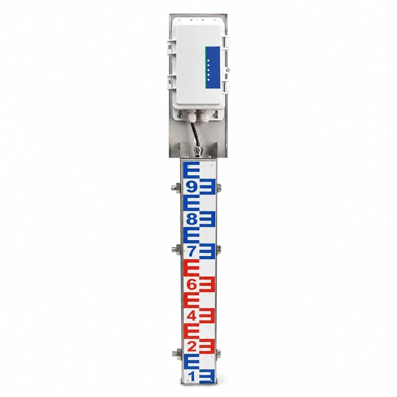
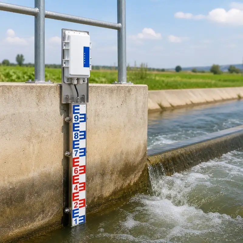
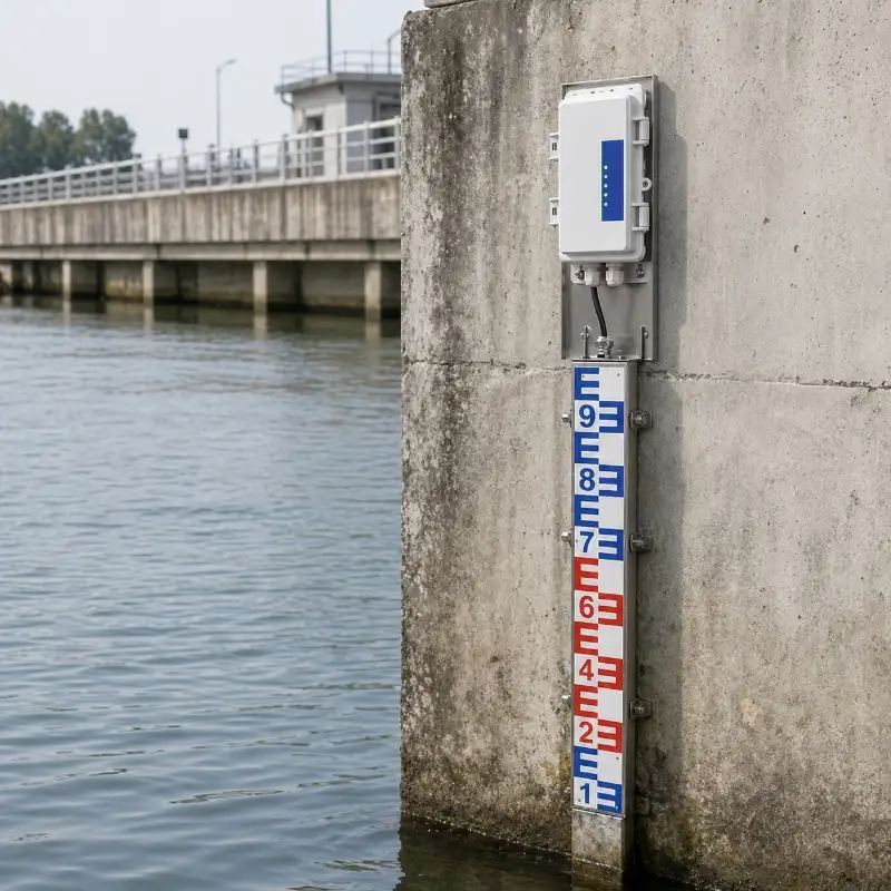
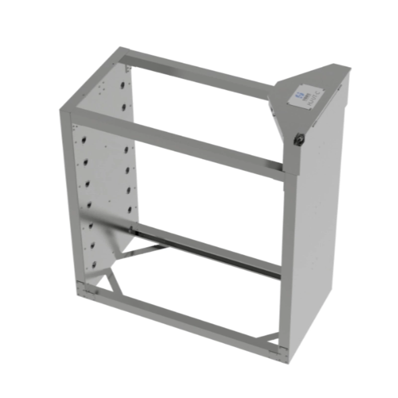
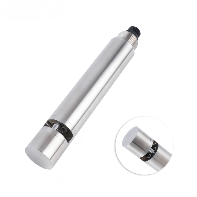
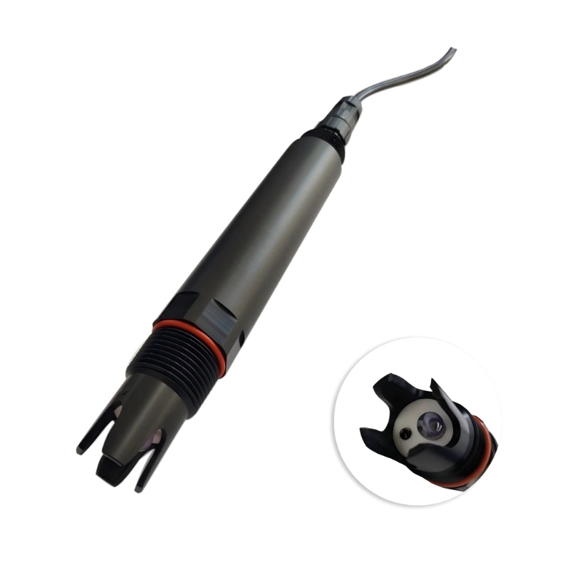
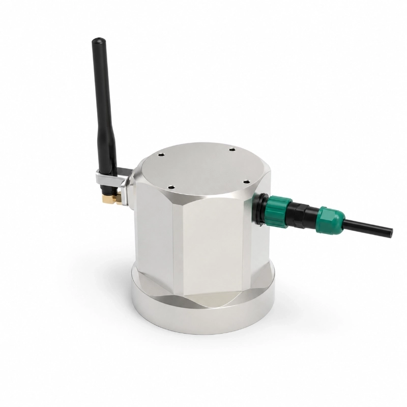
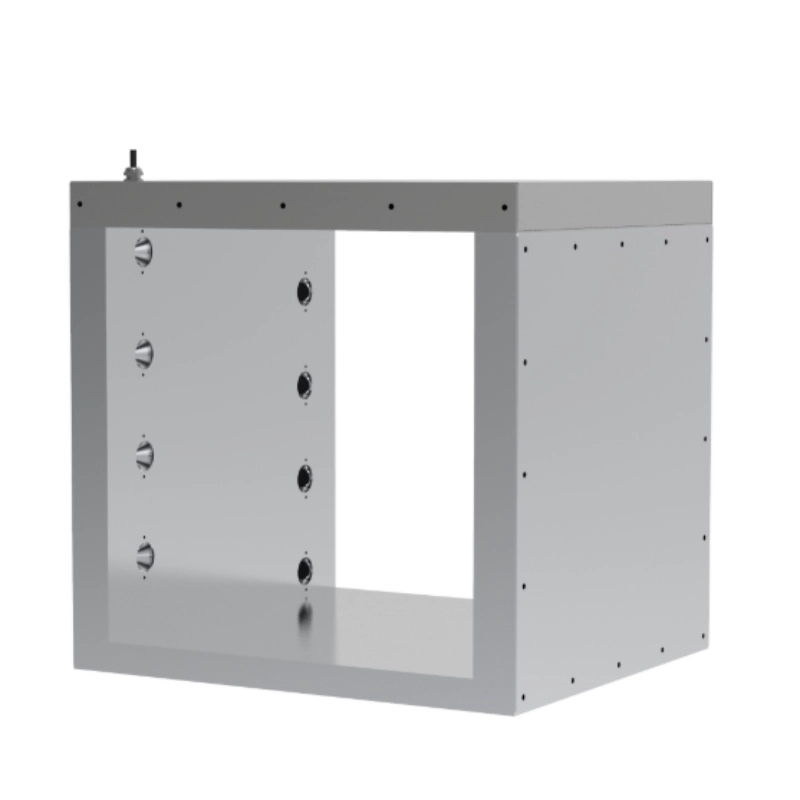
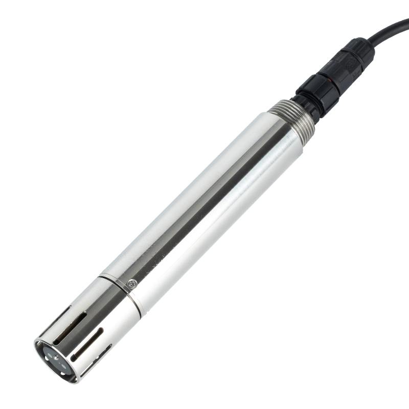
High-precision water level measurement: Supports full-range equal-accuracy measurement with optional 1 mm, 2 mm, 5 mm and 1 cm precision configurations.
Electronic electrode sensing: Measures water level by detecting the contact position of water on the electrode ruler.
Advanced processor chip: Uses an intelligent processor as the controller to improve measurement accuracy, stability and anti-interference performance.
Multiple output options: Supports RS485 Modbus, analog output and 4G signal transmission for different system integration needs.
Mobile and PC data viewing: Water level data can be uploaded to a monitoring platform for real-time viewing on mobile phones and computers.
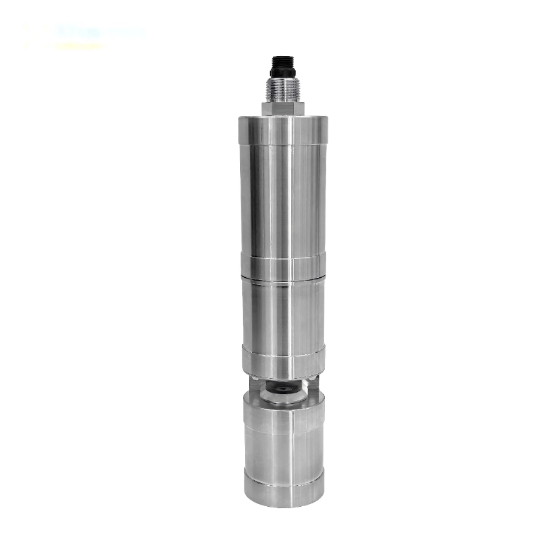
Stainless steel housing: Uses 304 stainless steel protective material for high corrosion resistance and mechanical durability.
Anti-corrosion and anti-aging design: Suitable for muddy water, corrosive liquids, sediments and outdoor water environments.
Automatic temperature compensation: Helps improve measurement reliability under changing water temperature conditions.
Zero drift control: Designed for accurate measurement with reduced drift during long-term monitoring.
Relay output support: RS485 and 4G versions can include one relay output for alarm linkage or upper and lower water level control.
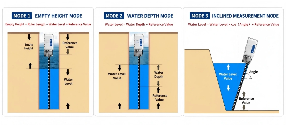
Multiple measurement modes: Supports empty height mode, water depth mode and inclined measurement mode to reduce hardware cost in different projects.
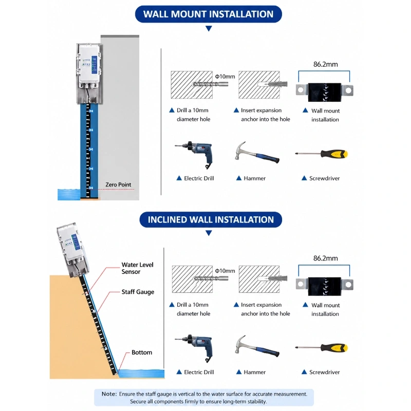
Wall-mounted installation: Supports vertical or inclined wall-mounted installation depending on site conditions.
Continuous water level monitoring for rivers, reservoirs, irrigation canals, hydropower facilities and urban flood warning projects.
The JW-DC-EWG(LC52) Electronic Water Gauge is designed for continuous and high-resolution water level monitoring in rivers, reservoirs, lakes, irrigation canals, hydropower facilities, drainage systems and urban flood-prone areas.
Unlike manual staff gauges that require on-site observation, the electronic water gauge automatically detects changing water levels and converts them into digital monitoring data. The measurements can be transmitted to a data logger, RTU, cloud platform or third-party monitoring system for real-time display, historical analysis and threshold-based warning.
The system is suitable for projects that require a clearly defined vertical measuring range, continuous water contact detection and reliable remote water level reporting.
JW-IoT can provide the electronic gauge together with data acquisition equipment, 4G or LoRaWAN communication, solar power, warning devices and a remote monitoring platform.
Contact JW-IoT for a project-specific water level monitoring configuration.
Product Overview
Water levels can change rapidly during heavy rainfall, upstream discharge, reservoir operation, irrigation scheduling, hydropower regulation and urban storm events.
Manual water level gauges provide a simple visual reference, but they require personnel to be physically present at the monitoring point. They cannot independently transmit real-time data or automatically issue alarms when the level rises beyond a defined threshold.
The JW-DC-EWG(LC52) electronic water gauge converts the changing water level into an electrical measurement signal. The data can be collected continuously and transmitted to a central monitoring platform.
This allows operators to:
View the current water level remotely
Observe rising and falling water trends
Compare measurements from multiple stations
Configure high-level and low-level alarms
Review historical water level records
Support flood warning and water dispatch decisions
An electronic water gauge uses vertically arranged sensing points or measuring sections to determine the position of the water surface.
When water reaches a sensing point, the electrical state of that section changes. The instrument identifies the highest activated point and converts it into a corresponding water level value.
A simplified measurement process is:
Water contacts sensing section → Electrical state changes → Controller identifies water level → Data is converted into a digital value → RTU transmits data to the platform
The exact internal detection structure may vary according to the product configuration, measuring range and required resolution.
Because the gauge measures along a defined vertical structure, it is particularly suitable for locations where:
The required measuring range is known
A fixed mounting structure is available
Direct contact with the water is acceptable
High-resolution level changes need to be detected
Operators want a digital alternative to manual staff gauges
Why Use an Electronic Water Gauge?
Automatic Monitoring
The gauge records water level changes automatically and reduces the need for continuous manual observation.
Clear Measuring Reference
Because the sensing structure is installed vertically along the measurement section, the relationship between gauge position and water level is direct and easy to verify.
High Resolution
The measurement resolution can be configured according to the sensor structure and project requirements, making the system suitable for applications that require detailed changes in water level.
Remote Data Transmission
Water level readings can be sent through an RTU or data logger to a cloud platform, private server, SCADA system or third-party application.
Alarm Capability
The monitoring system can issue warnings when the measured level exceeds predefined high-water, low-water or rate-of-rise thresholds.
Multi-Site Deployment
Several electronic water gauges can be connected to one monitoring platform to form a distributed river, canal, reservoir or urban flood monitoring network.
Typical Monitoring System Architecture
A complete electronic water gauge monitoring station normally contains four functional layers.
1. Water Level Sensing Layer
The electronic gauge detects the water level along its vertical measuring structure.
2. Data Acquisition Layer
A controller, data logger or RTU collects the sensor signal, applies the configured sampling interval and stores local records.
The field terminal transmits data through one of the following methods:
RS485 Modbus
4G LTE
LoRaWAN
Ethernet
NB-IoT
Project-specific telemetry
Other compatible communication protocols
4. Monitoring Platform Layer
The platform receives, stores and displays water level data. Depending on the project configuration, it can support:
Real-time water level display
Historical trend charts
GIS station mapping
Alarm records
Device status
Data export
User management
Multi-station comparison
API integration
Cloud deployment
Private server deployment
The typical data flow is:
Electronic Water Gauge → Data Logger or RTU → Communication Network → Cloud or Private Server → Dashboard and Warning System
Technical Specifications
The following values should be confirmed according to the final model and measuring range.
Parameter
Specification
Power Supply
DC 8–17 V
Water Level Accuracy
1 cm
Resolution
1 cm
Output Method
RS485 standard Modbus analog output 4G signal
Parameter Setting
Preconfigured by technical staff
Maximum Host Power Consumption
RS485 output 0.8 W analog output 1.2 W 4G output 1 W
Maximum Power per Gauge Section
0.05 W
Measuring Range
50 cm 100 cm 150 cm 200 cm 250 cm 300 cm 350 cm 400 cm 500 cm up to 950 cm
Installation Method
Wall-mounted
Mounting Hole Size
86.2 mm
Drilling Diameter
Φ10 mm
Host Protection Rating
IP68
Slave Gauge Protection Rating
IP68
Optional Accuracy
1 mm 2 mm 5 mm 1 cm
Output Expansion
One relay output for alarm linkage or water level control
Housing Material
304 stainless steel protective housing
Final range, segment spacing, material, enclosure protection, operating temperature, cable length and electrical specifications must follow the approved datasheet and quotation.
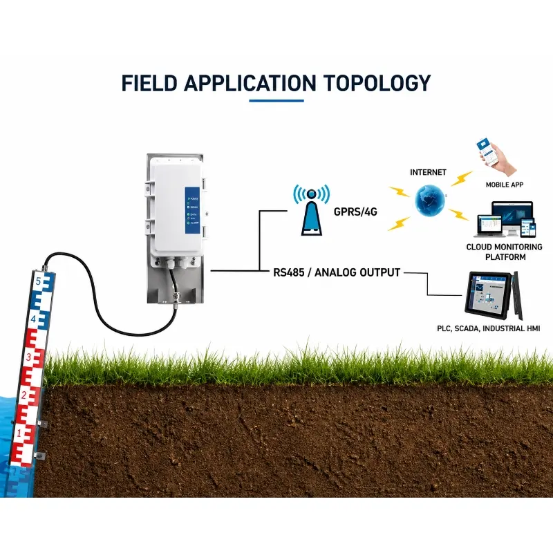
System Topology
Measurement Modes
Communication Options
RS485 Modbus
RS485 is suitable for connecting the water gauge to a nearby data logger, PLC or RTU. It provides stable wired communication for fixed monitoring stations.
4G LTE
4G allows the monitoring terminal to upload data directly to a remote server where cellular coverage is available.
LoRaWAN
LoRaWAN is suitable for projects with multiple monitoring points within the coverage area of one or more gateways. It can reduce cellular subscription requirements at individual sensor locations.
Ethernet
Ethernet may be used at hydropower stations, pumping stations, control rooms and other locations with existing wired network infrastructure.
Customized Telemetry
JW-IoT can evaluate MQTT, TCP, HTTP and industry-specific communication requirements according to the project platform.
The water gauge and associated communication terminal can be configured with:
Mains power
DC power
Solar panel
Rechargeable battery
Solar charge controller
Mains and battery backup
Project-specific hybrid power
For solar-powered monitoring stations, the panel and battery capacity should be calculated according to:
Sensor power consumption
RTU power consumption
Transmission interval
Local solar radiation
Seasonal weather
Required backup duration
Optional camera or alarm equipment
Alarm and Warning Functions
The monitoring system can be configured with several alarm methods.
High-Water-Level Alarm
An alarm is triggered when the water level exceeds a predefined safety or operational threshold.
Low-Water-Level Alarm
Low-level alarms can support reservoir operation, irrigation canal management, pumping stations and hydropower facilities.
Rapid-Rise Alarm
The platform can compare measurements over time and generate an alarm when the water level rises faster than the configured rate.
Communication Failure Alarm
The system can indicate when a station stops transmitting data for longer than the permitted period.
Low-Power Alarm
Solar and battery-powered stations can report abnormal supply voltage or low battery status.
Thresholds should be configured by the project owner according to local hydrological conditions, engineering requirements and emergency response procedures.
A water level alarm indicates that a configured measurement condition has been reached. It should not be treated as a complete flood forecast without rainfall, upstream discharge, terrain and other hydrological information.
Installation Methods
The electronic water gauge should be installed vertically along a stable structure.
Possible mounting locations include:
Bridge piers
Retaining walls
Riverbank structures
Reservoir walls
Canal sidewalls
Hydropower intake structures
Gate structures
Drainage channels
Culverts
Flood monitoring poles
Dedicated monitoring frames
Installation Requirements
Keep the gauge vertical.
Confirm the zero reference elevation.
Install the sensing section within the expected water level range.
Use a rigid mounting structure.
Protect cables from flow impact, debris and vandalism.
Avoid locations with excessive sediment deposition.
Avoid installation directly beside strong turbulence where possible.
Confirm that floating objects will not repeatedly strike the sensor.
Provide safe maintenance access.
Survey the gauge elevation before commissioning.
Compare the electronic reading with a known physical reference.
For hydrological projects, the installation elevation and reference datum should be recorded in the station documentation.
Application Scenarios
River Water Level Monitoring
The electronic water gauge can continuously measure river levels at bridges, monitoring sections, tributaries and flood-prone reaches.
It can support:
Flood-season observation
Water level trend analysis
River management
Emergency warning
Remote hydrological station construction
Reservoir Water Level Monitoring
Reservoir operators can use the gauge to observe storage-related level changes and configure high- and low-level alarms.
Typical locations include:
Reservoir dams
Intake structures
Spillway areas
Observation wells
Auxiliary reservoirs
Irrigation Canal Monitoring
Canal water levels affect water distribution, gate control and irrigation scheduling.
The electronic gauge can be used for:
Main canal monitoring
Branch canal monitoring
Gate upstream and downstream levels
Water allocation management
Canal operation verification
For projects requiring both level and flow measurement, consider integrating an open channel flow meter.
Hydropower Water Level Monitoring
Hydropower facilities may require water level measurements at several locations, including:
Forebay
Tailwater
Intake channel
Reservoir
Gate upstream
Gate downstream
Diversion channel
The data can be integrated with PLC, SCADA or plant management systems according to project requirements.
Urban Flood Monitoring
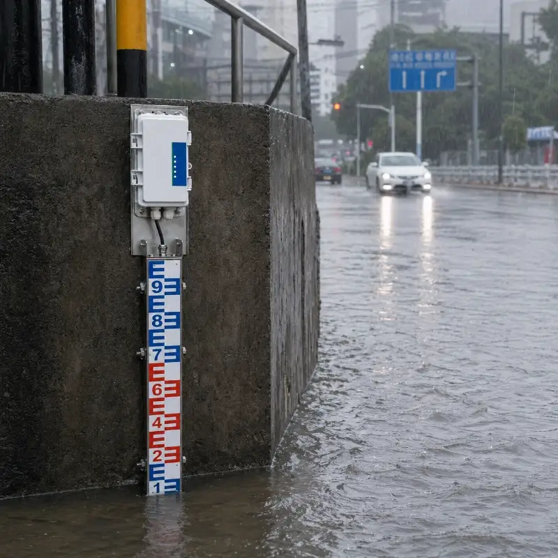
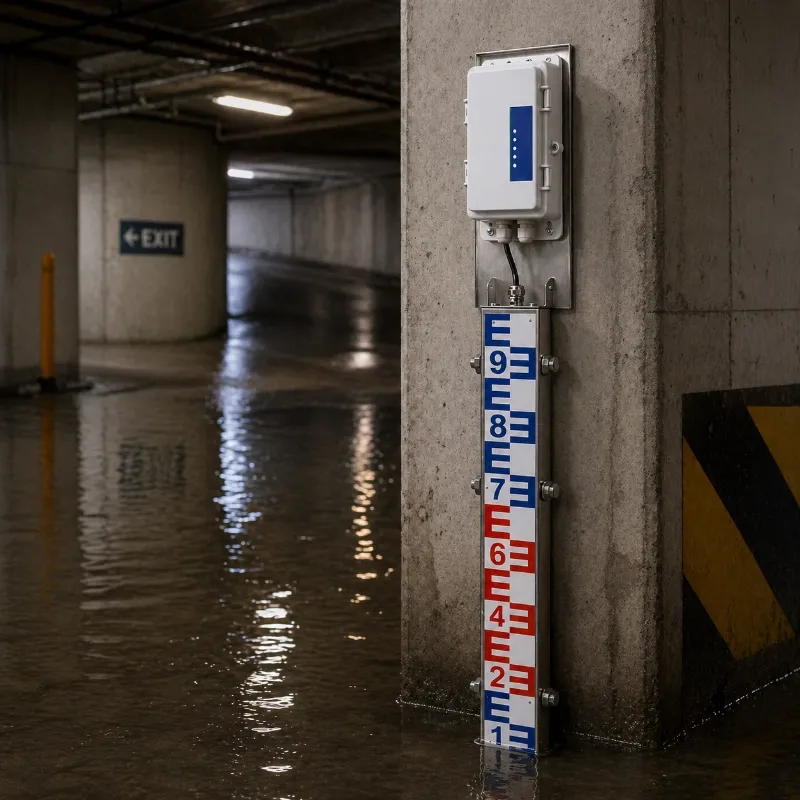
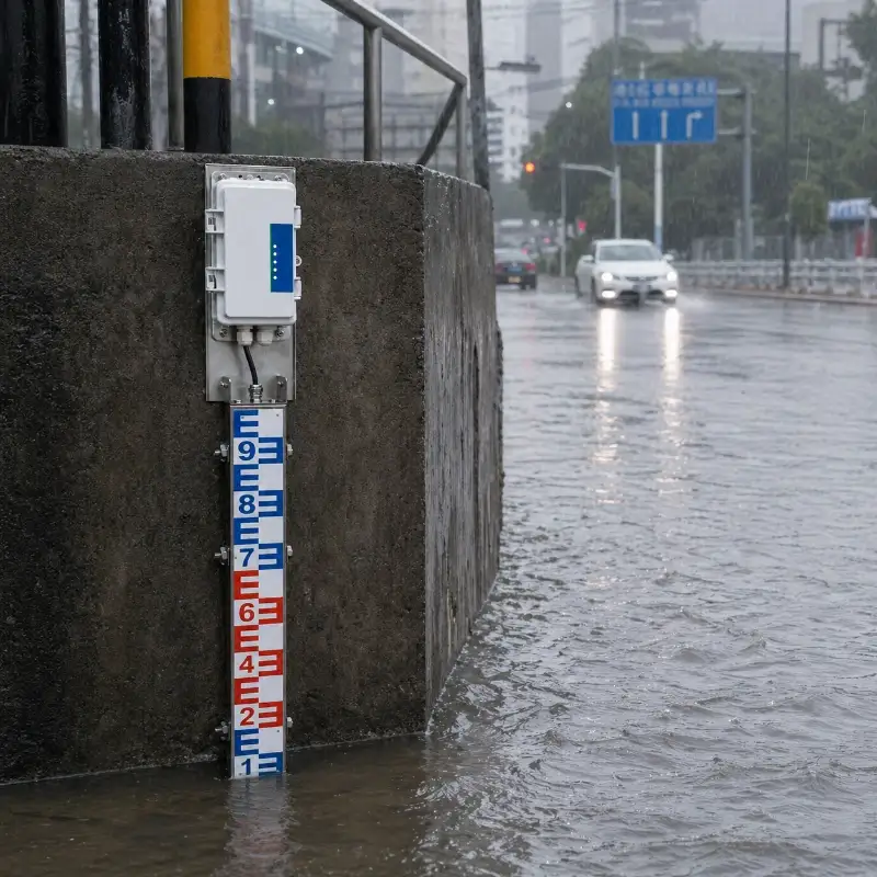
For city-scale deployments, one electronic water gauge can monitor a single road, underpass, or drainage point. Multiple terminals can be connected to a central platform through a complete urban flood monitoring system for unified alarms, GIS visualization, and emergency response.
Lake and Wetland Monitoring
The gauge can support long-term level observation in lakes, wetlands and ecological water management areas where a stable mounting structure is available.
Pumping Station Monitoring
Water level data can be used to support pump start-stop logic, operational alarms and remote management.
Electronic Water Gauge vs Other Water Level Sensors
Different water level technologies are suitable for different site conditions.
Technology
Measurement Method
Contact with Water
Main Advantages
Typical Limitations
Electronic water gauge
Detects activated sensing sections
Yes
Direct level reference, configurable resolution, easy verification
Requires fixed vertical installation and contact with water
Radar water level sensor
Measures distance using radar waves
No
Non-contact, low maintenance, suitable for rivers and reservoirs
Requires clear measurement path and suitable mounting height
Ultrasonic water level sensor
Measures distance using sound waves
No
Non-contact and relatively simple installation
Can be affected by temperature, condensation, foam and turbulence
Pressure water level sensor
Measures hydrostatic pressure
Yes
Suitable for wells, reservoirs and submerged applications
Requires immersion and may need compensation or cleaning
Manual staff gauge
Visual scale reading
Yes
Simple, inexpensive and easy to understand
Requires on-site personnel and cannot transmit data automatically
Choose an Electronic Water Gauge When:
A fixed vertical measurement structure is available
The measuring range is clearly defined
Direct contact measurement is acceptable
High-resolution level detection is required
A visible or physically verifiable level reference is preferred
Digital output and remote transmission are required
Consider Radar When:
Non-contact measurement is preferred
Floating debris or sediment could affect contact sensors
The site has a bridge or overhead mounting structure
JW-IoT can configure the electronic water gauge system according to:
Required measuring range
Required resolution
Mounting structure
Installation environment
Output interface
Communication method
Sampling interval
Data transmission frequency
Solar power requirements
Battery backup duration
Local alarm devices
Cloud platform requirements
Private server deployment
Third-party API
PLC or SCADA integration
Data protocol
Enclosure requirements
Branding and OEM needs
Information Required Before Quotation
To prepare an accurate configuration, please provide:
Installation country and project location
Application type
Expected minimum and maximum water levels
Required measuring range
Required resolution
Installation structure or site photographs
Available power supply
Mobile or LoRaWAN network conditions
Required communication protocol
Number of monitoring stations
Cloud or private platform preference
Required alarm method
Required cable length
Integration requirements
Maintenance Recommendations
Although the electronic water gauge is designed for long-term field monitoring, regular inspection remains necessary.
Recommended maintenance includes:
Remove attached sediment, algae and debris
Inspect sensing sections
Check mounting brackets
Check cable protection
Verify the zero reference
Compare readings with a physical reference
Inspect terminal enclosures
Check solar panels and batteries
Confirm communication status
Review abnormal or missing data
Inspect the site after floods or severe storms
The maintenance interval should be adjusted according to sediment, water quality, biological growth, debris load and flood frequency.
Why Choose JW-IoT?
JW-IoT provides integrated monitoring solutions covering sensors, data acquisition, communication, power supply and remote platforms.
Our project support can include:
Electronic water level gauges
Radar and pressure water level sensors
Open channel flow meters
Rain gauges
Data loggers and RTUs
4G and LoRaWAN communication
Solar power systems
Cloud monitoring platforms
Private-server deployment
API and protocol integration
Installation guidance
OEM and white-label support
Remote technical assistance
Our water sensors support water level, flow and water quality monitoring for rivers, reservoirs, irrigation, drainage, environmental monitoring and smart water projects.
Build a Remote Water Level Monitoring System
A reliable water level monitoring project requires more than one sensor. Measuring range, mounting, power, communication, warning rules and platform integration must be considered together.
Send JW-IoT your site information, required measuring range, number of monitoring points, communication conditions and platform requirements.
Contact JW-IoT to receive a recommended electronic water gauge configuration.
FAQ
Q
1. What is an electronic water gauge used for?
A
An electronic water gauge is used to monitor water levels in rivers, reservoirs, lakes, canals, hydropower facilities, drainage channels and flood-prone locations.
Q
2. How does the electronic water gauge measure water level?
A
The gauge identifies which sensing sections are in contact with water and converts the highest activated measurement point into a digital water level value.
Q
3. Is the electronic water gauge the same as a manual staff gauge?
A
No. A manual staff gauge requires visual observation. An electronic water gauge detects the water level automatically and can transmit the data remotely.
Q
4. Can JW-IoT customize the measuring range?
A
Yes. JW-IoT can configure the measuring structure and range according to the expected minimum and maximum water levels.
Q
5. Does it support RS485 Modbus?
A
RS485 Modbus can be provided according to the selected model and project configuration. The final output and protocol should be confirmed in the technical quotation.
Q
6. Can the water level data be transmitted through 4G or LoRaWAN?
A
Yes. The gauge can connect to a compatible JW-IoT data logger or RTU for 4G, LoRaWAN or other remote communication.
Q
7. Can the system issue flood warnings?
A
Yes. The platform can generate alarms based on high water level, rapid rise, communication failure or other configured conditions. The alarm rules must be set according to the local flood response plan.
Q
8. Is it suitable for irrigation canals?
A
Yes. The gauge can monitor canal water levels upstream and downstream of gates or at selected control sections. It can also be combined with flow monitoring equipment.
Q
9. Can JW-IoT integrate the gauge with an existing platform?
A
Yes. JW-IoT can support integration through standard or customized communication protocols, subject to technical evaluation.
 +86 13520127780
  info@jingelway.com