+86 13520127780
 info@jingelway.com









Pressure Monitoring in AI Data Center Liquid Cooling Systems
Release time: 2026-09-29
AI Data Centers Are Changing the Way Cooling Systems Are Monitored
The rapid growth of artificial intelligence, GPU computing and high-performance computing is increasing heat density inside modern data centers.
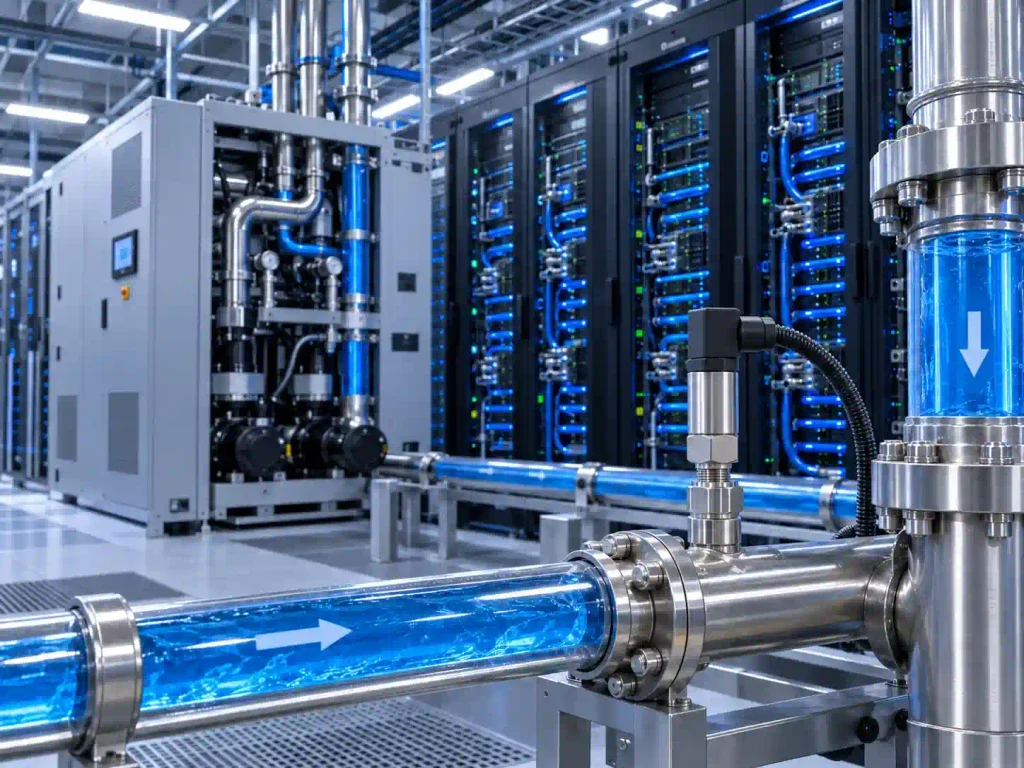
As computing density rises, liquid cooling is becoming increasingly important for high-density AI infrastructure. Unlike conventional air-cooling systems, liquid-cooling architectures introduce an additional fluid network that must be carefully managed.
A typical liquid-cooled data center may include:
- Coolant Distribution Units (CDUs)
- Facility water systems
- Technology cooling systems or secondary coolant loops
- Pumps
- Supply and return pipelines
- Distribution manifolds
- Cold plates
- Flow, pressure and temperature monitoring devices
- Leak detection systems
In these systems, cooling performance depends not only on coolant temperature but also on flow rate and hydraulic pressure throughout the cooling circuit.
Schneider Electric notes that liquid-cooled AI servers require specific flow, pressure and coolant inlet temperature conditions, while the CDU is responsible for delivering those conditions.
This makes pressure measurement an important part of the overall monitoring architecture.
Why Pressure Matters in an AI Data Center Liquid Cooling System
Pressure provides information about the hydraulic condition of the cooling loop.
Coolant must move through pipes, valves, connectors, filters, manifolds and cold plates before returning to the CDU. Every component introduces some degree of resistance to flow.
Schneider Electric explains that each component in the technology cooling system—including pipes, valves, connectors, flow meters, pressure sensors and cold plates—contributes to the total pressure drop of the loop. As flow increases, pressure drop also increases.
Monitoring pressure at selected locations therefore helps system integrators understand whether the hydraulic system is operating within its intended range.
Pressure data can be useful for:
- Monitoring supply and return line conditions
- Observing pump operating conditions
- Evaluating pressure differences across a cooling loop
- Supporting coolant distribution management
- Providing input to CDU or PLC control systems
- Identifying abnormal hydraulic conditions for further investigation
Pressure should not be considered independently, however. A reliable cooling monitoring architecture normally combines pressure with flow, temperature and leak detection.
Vertiv describes modern CDUs as systems that monitor and control parameters including temperature, pressure and flow rate in order to maintain liquid-cooling operation.
Where Can Pressure Transmitters Be Installed?
The exact sensor locations depend on the CDU architecture, cooling-loop design and server manufacturer requirements.
However, several positions are commonly relevant.
1. CDU Supply Line
The CDU supply line delivers conditioned coolant toward server racks or cooling manifolds.
A pressure transmitter installed on the supply side can provide continuous information about the pressure being delivered by the CDU into the secondary cooling network.
This measurement may be used together with flow and temperature values to provide the control system with a clearer understanding of the coolant supply condition.
For liquid-cooled IT equipment, manufacturers typically specify configuration-dependent pressure differential and flow requirements. ASHRAE notes that these values vary according to the equipment, water temperature and heat load.
2. CDU Return Line
After absorbing heat from server cold plates, the coolant returns to the CDU.
Monitoring return-line pressure provides an additional reference point for evaluating the hydraulic state of the cooling network.
When pressure is measured at both the supply and return sides, the values can also support analysis of pressure differences across parts of the system.
This is especially useful because the secondary cooling network contains multiple components that create pressure loss.
3. Pump Inlet and Outlet
Pumps are responsible for maintaining coolant circulation.
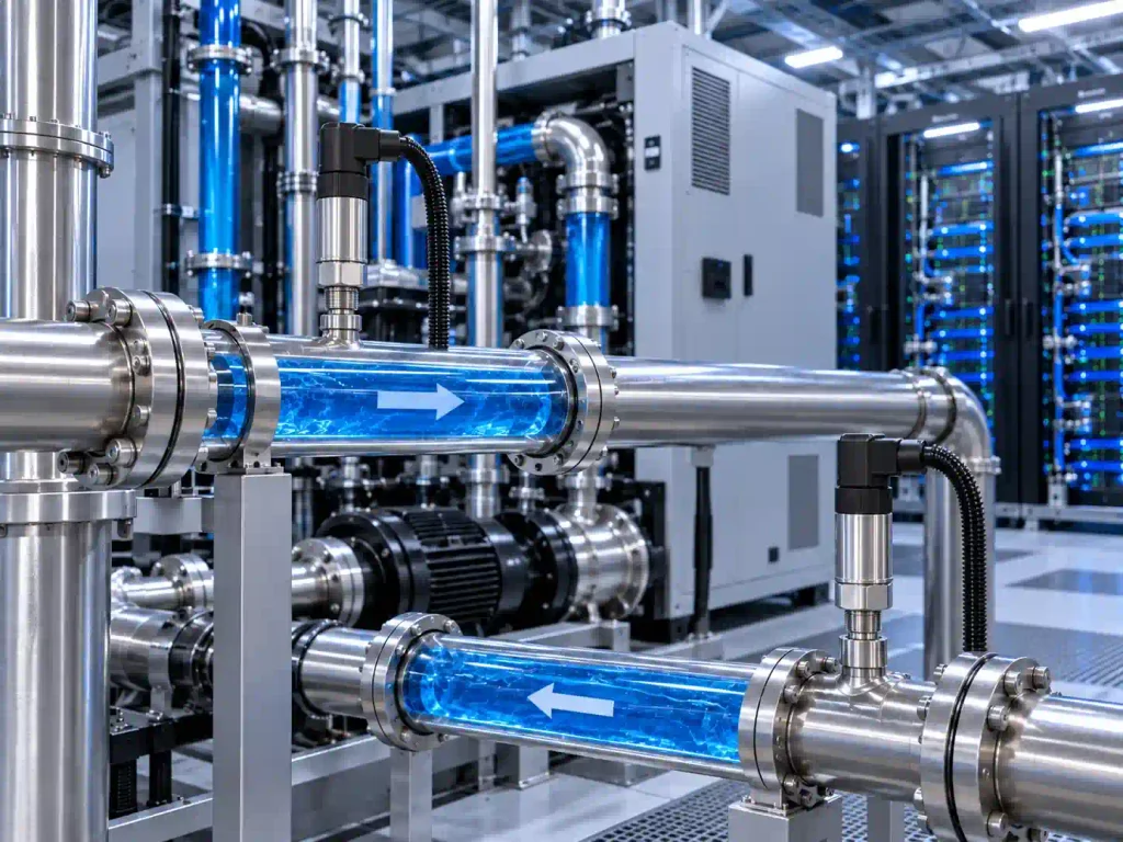
Pressure measurement on the inlet and outlet sides of a pump can provide useful operating data for control and commissioning.
For example, pump-related pressure information can be evaluated together with:
- Coolant flow rate
- Pump speed
- Supply temperature
- Return temperature
- System load
The purpose is not simply to measure one pressure value, but to understand how the hydraulic system responds when cooling demand changes.
In modern CDU designs, pumps may adjust coolant conditions according to the operating requirements of the IT cooling loop. Schneider Electric describes the CDU as a central unit that pumps coolant through an isolated loop and adjusts coolant flow and temperature for thermal management.
4. Cooling Distribution Manifolds
Distribution manifolds divide the coolant flow between racks, servers or multiple cold-plate branches.
As the number of branches increases, hydraulic balancing becomes increasingly important.
Pressure monitoring around manifolds can help provide additional information about coolant distribution conditions.
This becomes particularly relevant in high-density computing environments where different server branches may operate at different thermal loads.
In research discussed by Vertiv on pumped two-phase direct-to-chip cooling, pressure differential was actively regulated across individual cooling circuits to support consistent fluid distribution under changing IT loads.
The exact pressure range and control strategy vary between cooling technologies, so sensor selection should always follow the actual system specification rather than applying one universal value.
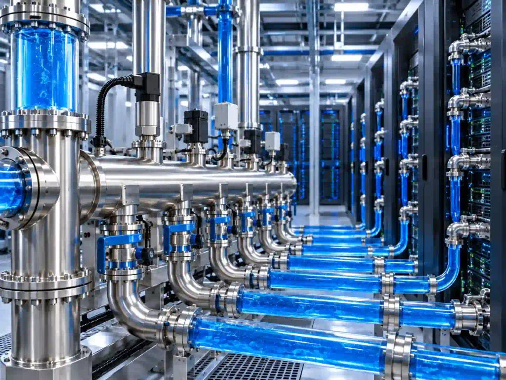
5. Secondary Cooling Loop
Many liquid-cooled data centers separate the IT cooling circuit from the facility cooling system.
The CDU acts as the interface between these two fluid networks.
Vertiv describes the secondary fluid network as the section between the facility loop and server racks, with the CDU transferring heat while regulating coolant temperature, pressure and flow.
Pressure transmitters installed along the secondary loop can therefore become part of the overall cooling monitoring system.
Potential measurement locations may include:
- CDU outlet
- CDU inlet
- Main supply header
- Main return header
- Rack-level manifold
- Pump discharge line
The final layout should be determined by the cooling-system designer.
Pressure, Flow and Temperature Should Be Monitored Together
A pressure transmitter alone cannot provide a complete picture of liquid-cooling performance.
A more useful monitoring architecture combines several types of sensing.
Pressure Monitoring
Pressure transmitters provide information about hydraulic conditions inside the coolant circuit.
Flow Monitoring
Flow sensors measure how much coolant is moving through the cooling loop.
This is important because cooling capacity depends partly on maintaining sufficient coolant circulation.
Temperature Monitoring
Temperature sensors can measure:
- CDU supply temperature
- CDU return temperature
- Pipe temperature
- Coolant temperature at selected monitoring points
The difference between supply and return temperatures provides useful information about heat transfer through the cooling loop.
Leak Detection
Leak detection should be treated as a dedicated monitoring function.
Pressure changes may indicate that a hydraulic condition has changed, but pressure measurement should not be presented as a replacement for a leak-detection system.
Modern CDU designs can combine closed-loop piping with dedicated leak detection and fluid monitoring.
For a complete cooling monitoring strategy, these measurements can be integrated into a common controller or monitoring platform.
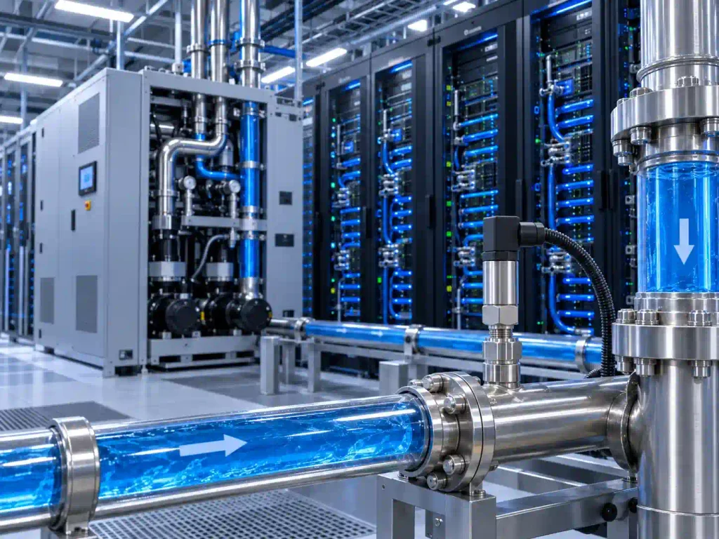
A typical architecture may look like:
Pressure + Flow + Temperature + Leak Detection
↓
CDU Controller / PLC / Data Acquisition System
↓
BMS / DCIM / SCADA / Monitoring Platform
How to Select a Pressure Transmitter for Liquid Cooling
A pressure transmitter used in a data center cooling circuit should be selected according to the actual engineering requirements.
1. Confirm the Pressure Range
The first step is determining the expected operating pressure.
A transmitter should provide enough measurement range for normal conditions while also accommodating expected pressure fluctuations.
Using a range that is far wider than required may reduce useful measurement resolution.
The correct range should therefore be determined from the CDU and cooling-loop design.
2. Select the Pressure Type
Pressure transmitters may measure:
- Gauge pressure
- Sealed gauge pressure
- Absolute pressure
The correct measurement method depends on how the cooling system is designed and how pressure values are used by the controller.
For most applications, this should be confirmed with the CDU or system integrator before sensor selection.
3. Confirm Coolant Compatibility
The wetted material of the pressure transmitter must be compatible with the coolant.
Different liquid-cooling systems may use different fluid compositions.
For this reason, material selection should not be based only on the pressure range.
The JW-IoT pressure transmitter provides diaphragm options including:
- 316L stainless steel
- C-276
- TC4
The appropriate option should be evaluated according to the actual coolant and system requirements.
4. Choose the Correct Signal Output
The pressure transmitter must communicate with the system controller.
Common industrial signals include:
- 4–20 mA
- Voltage output
- RS485
A 4–20 mA signal can be suitable for conventional industrial control architectures, while RS485 can support digital communication depending on the integration design.
The choice depends on:
- Controller interface
- Wiring distance
- Data acquisition architecture
- PLC or CDU controller requirements
5. Check the Process Connection
Mechanical integration is equally important.
The sensor must connect correctly to the pipe, manifold or equipment port.
Before ordering a pressure transmitter, confirm:
- Thread type
- Thread size
- Installation position
- Available mounting space
- Required sealing method
Custom process connections may be needed for OEM or CDU integration projects.
6. Consider Environmental Protection
Data centers are controlled environments, but pressure sensors may still be installed near:
- Pumps
- Coolant manifolds
- CDUs
- Pipe connections
- Areas where condensation or coolant exposure may occur
An appropriate ingress-protection rating can therefore be useful for long-term operation.
JW-PM01X(JY05) High Accuracy Pressure Transmitter
For projects requiring industrial pressure monitoring, the JW-PM01X(JY05) High Accuracy Pressure Transmitter provides multiple configuration options for pressure measurement and industrial system integration.
The transmitter uses a silicon pressure sensing element with an isolation diaphragm and signal-conditioning electronics for stable industrial pressure measurement.
Main Specifications
| Parameter | Specification |
| Pressure Range | -100 kPa to 1000 kPa; 0–1 to 100 MPa |
| Pressure Type | Gauge, sealed gauge, absolute |
| Accuracy Classes | 0.1, 0.2 (0.25), 0.5 |
| Output Options | 4–20 mA, 0.5–4.5 VDC, 0–10 VDC, IIC, RS485 |
| Response Time | <1 ms |
| Overload Capacity | 200% |
| Working Temperature | -20°C to 85°C |
| Diaphragm Materials | 316L, C-276, TC4 |
| Process Connection | M20×1.5 or customized |
| Electrical Connection | DIN43650A or customized |
| Protection Grade | IP65 / IP66 / IP67 / IP68 |
All specifications above are based on the current JW-IoT product page.
For AI data center liquid-cooling projects, the product should be selected according to actual coolant compatibility, pressure range, mechanical connection and controller interface requirements.
Example Monitoring Architecture for an AI Liquid-Cooling Project
A practical monitoring system could contain multiple sensing points rather than relying on one device.
For example:
CDU Level
Monitor:
- Supply pressure
- Return pressure
- Coolant temperature
- Flow rate
Pump Level
Monitor:
- Pump inlet pressure
- Pump outlet pressure
- Flow rate
- Pump operating status
Distribution Level
Monitor:
- Main header pressure
- Distribution manifold conditions
- Branch flow
Rack or Server Level
Depending on the system design:
- Coolant supply temperature
- Coolant return temperature
- Flow condition
- Leak detection
The sensors can then connect to a controller, PLC or data acquisition system and subsequently to the data-center monitoring platform.
This architecture allows pressure data to become part of a wider cooling-system dataset rather than an isolated measurement.
FAQ
1. Why is pressure monitoring important in AI data center liquid cooling?
Liquid cooling requires coolant to move through pumps, pipes, valves, manifolds and cold plates.
These components create hydraulic resistance and pressure drop.
Monitoring pressure helps provide visibility into the operating condition of the coolant circuit and supports system control, commissioning and troubleshooting.
2. Where should pressure sensors be installed in a liquid-cooling system?
Potential locations include CDU supply and return lines, pump inlet and outlet pipes, distribution manifolds and secondary cooling loops.
The final location should follow the hydraulic design of the specific project.
3. Can pressure monitoring detect a coolant leak?
Pressure data may indicate that hydraulic conditions have changed, but it should not be used as a substitute for dedicated leak detection.
Liquid-cooling systems should use purpose-designed leak-monitoring methods where required.
4. Should pressure and flow be monitored together?
In many systems, yes.
Pressure and flow describe different aspects of the coolant circuit.
Combining pressure with flow and temperature measurements provides a more complete understanding of cooling-system operation.
5. What output signals are available from the JW-PM01X(JY05)?
The transmitter supports 4–20 mA, 0.5–4.5 VDC, 0–10 VDC, IIC and RS485 output options.
6. Can the process connection be customized?
Yes. The standard process connection listed on the product page is M20×1.5, and customized connections are available according to project requirements.
Building Better Visibility into AI Data Center Cooling
As AI and high-performance computing increase rack-level heat density, data center cooling is becoming a more integrated engineering discipline.
The CDU no longer functions simply as a heat exchanger.
It is part of a controlled fluid system where temperature, flow, pressure and coolant condition must work together.
Pressure monitoring contributes another layer of visibility into that system.
For CDU manufacturers, cooling-system integrators and data-center engineering teams, the important question is therefore not simply:
“Which pressure sensor should we use?”
The better questions are:
- What is the operating pressure range?
- What coolant will contact the sensor?
- Where should the pressure be measured?
- Which signal does the controller require?
- Which process connection fits the cooling loop?
- How will pressure data work together with temperature, flow and leak monitoring?
JW-IoT provides industrial pressure measurement solutions that can be configured according to pressure range, output interface and process-connection requirements.
👉 Explore the JW-PM01X(JY05):
High Accuracy Pressure Transmitter for Industrial Process Measurement
For AI data center liquid-cooling projects, provide your coolant type, pressure range, process connection and required output signal so the appropriate pressure-sensing configuration can be evaluated.