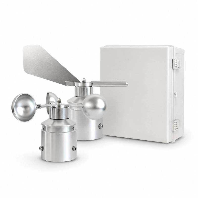
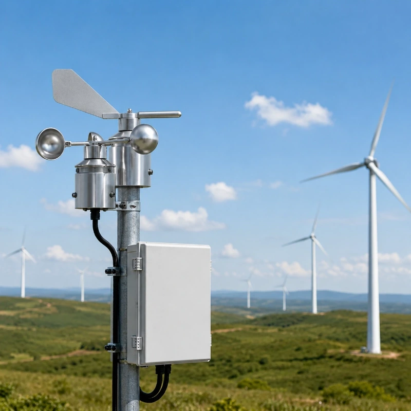
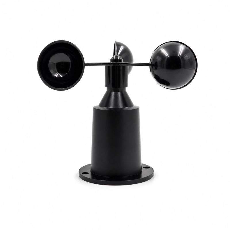
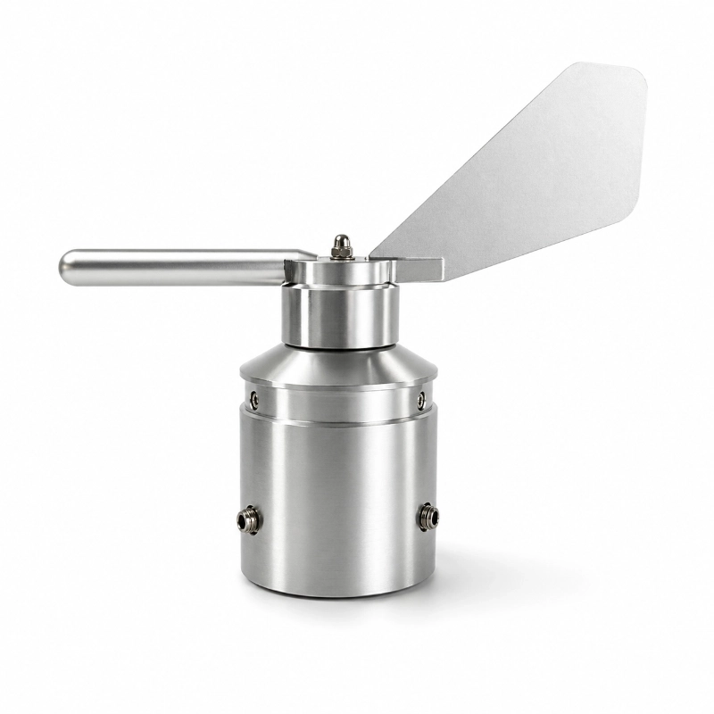
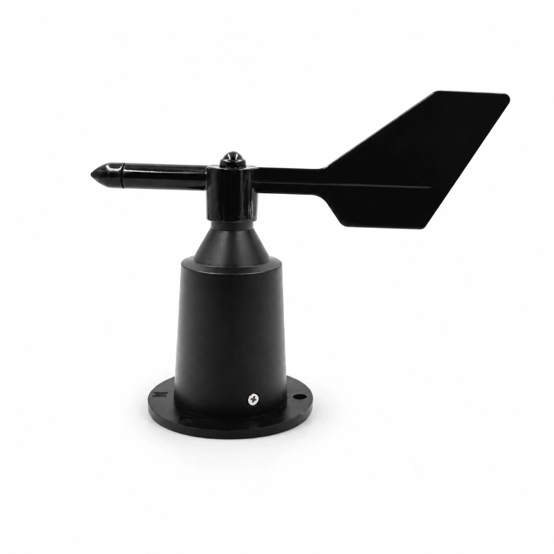
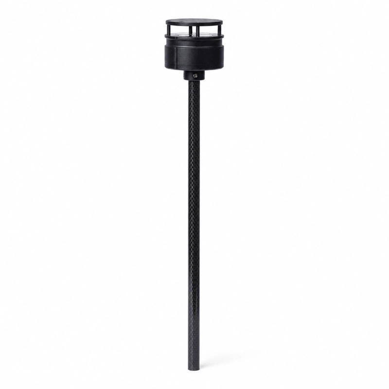
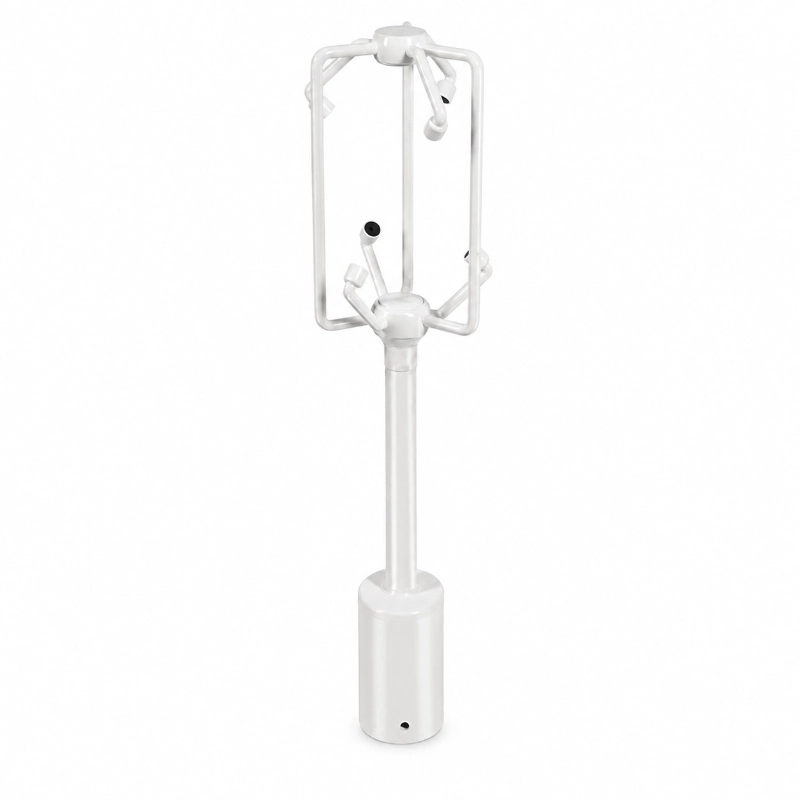
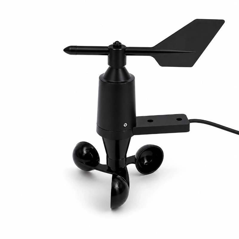
The JW-CF-5J(LC39) Wind Speed and Direction Sensor is a professional mechanical wind-monitoring instrument developed for wind farms, wind-resource assessment, meteorological towers and renewable-energy monitoring systems.
The sensor combines a cup anemometer, wind vane and environmental sensing channels to provide continuous measurement of:
Real-time wind speed
Instantaneous wind speed
Average wind speed
Maximum wind speed
Minimum wind speed
Five-minute average wind speed
Wind-speed standard deviation
Real-time wind direction
Average wind direction
Maximum and minimum wind direction
Five-minute average wind direction
Ambient temperature
Relative humidity
Atmospheric pressure
With a wind-speed range up to 75 m/s, a low starting threshold below 0.4 m/s, 0–360° wind-direction measurement and IP66 outdoor protection, the sensor is suitable for long-term monitoring in exposed wind-energy and meteorological environments.
The collected data can be transmitted to a wind data-acquisition instrument, automatic weather station, SCADA system, local controller or remote monitoring platform.
What Is a Wind Speed and Direction Sensor?
A wind speed and direction sensor measures two fundamental properties of airflow:
Wind speed describes how fast the air is moving.
Wind direction describes the direction from which the wind is coming.
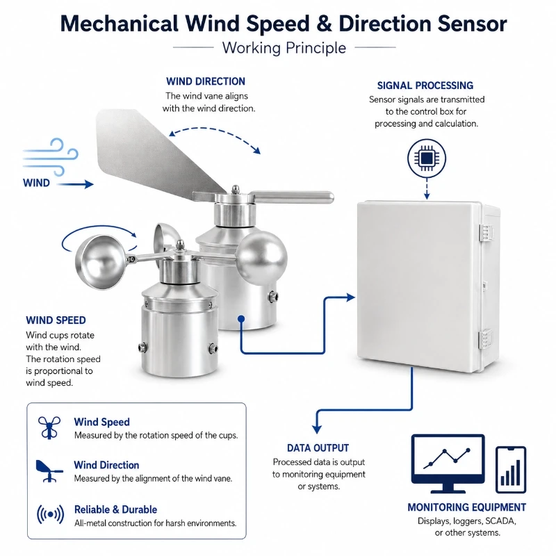
The JW-CF-5J(LC39) uses:
Rotating wind cups for wind-speed measurement;
A wind vane for wind-direction measurement;
An internal data-acquisition system for signal processing and output.
When wind moves the cups, the rotating mechanism generates a signal proportional to wind speed.
The wind vane aligns with the airflow and produces a direction value referenced to the sensor’s installed north position.
Why Wind Farms Need Local Wind Monitoring
Wind conditions can vary significantly across one wind farm because of:
Terrain
Elevation
Turbine layout
Forests
Hills
Coastal exposure
Wake effects
Seasonal weather patterns
Local turbulence
A regional weather station may not represent the actual wind conditions at a turbine site or measurement mast.
Local wind monitoring can support:
Wind-resource assessment
Site comparison
Turbine operating analysis
Extreme-wind warning
Wind-direction analysis
Maintenance planning
Meteorological reporting
Environmental monitoring
SCADA data verification
Wind Resource Assessment vs Turbine Operation Monitoring
These applications use wind data differently.
Wind Resource Assessment
Wind-resource assessment normally focuses on:
Long-term average wind speed
Wind-speed distribution
Dominant wind direction
Seasonal variation
Turbulence indicators
Vertical wind shear
Extreme wind events
Site-to-site comparison
The purpose is to understand the available wind resource before or during project development.
Turbine Operation Monitoring
Turbine-site monitoring may focus on:
Current wind speed
Maximum wind speed
Gust events
Wind-direction changes
Turbine yaw context
Weather-related shutdown conditions
Maintenance safety
Comparison with turbine SCADA data
The sensor itself provides wind and environmental data. Final turbine-control decisions should follow the wind-turbine manufacturer’s control system and safety requirements.
Understanding the Wind Data Outputs
Real-Time Wind Speed
Real-time wind speed represents the current measured wind condition at the selected sampling interval.
It can support:
Live dashboard display
Operational monitoring
Strong-wind alarms
Maintenance safety decisions
Instantaneous Wind Speed
Instantaneous values help detect short-term wind fluctuations and rapid changes.
The sampling and filtering method should be confirmed when the project requires a specific definition of instantaneous wind.
Average Wind Speed
Average wind speed reduces short-term fluctuations and provides a more stable representation of local wind conditions.
Average values may be calculated over:
One minute
Five minutes
Ten minutes
Another project-defined period
The product currently supports five-minute average wind-speed and wind-direction data.
Maximum Wind Speed
Maximum wind speed records the highest value observed during the selected reporting interval.
It can support:
Extreme-wind assessment
Alarm generation
Structural-risk analysis
Operational event review
Wind-Speed Standard Deviation
Wind-speed standard deviation describes how much wind speed varies around its average value.
A higher standard deviation may indicate more variable or turbulent wind conditions.
It should not automatically be treated as a complete turbulence-intensity measurement unless the sampling frequency, averaging period and calculation method meet the project requirement.
Wind Direction
Wind direction supports:
Dominant-wind analysis
Turbine yaw context
Wind-farm layout studies
Wake-effect analysis
Pollution-dispersion studies
Safety monitoring
The sensor must be aligned correctly during installation so that its direction output corresponds to geographic north.
Technical Specifications
Parameter
Measurement Range
Resolution
Accuracy
Wind Speed
0 to 75 m/s
0.1 m/s
±0.5 m/s ≤20 m/s or ±3% >20 m/s
Wind Direction
0 to 360°
<1°
±2°
Air Pressure
10 to 1100 hPa
0.1 hPa
≤±0.5 hPa
Average Wind Speed
0 to 75 m/s
0.1 m/s
±0.3 m/s
Maximum Wind Speed
0 to 75 m/s
0.1 m/s
±0.3 m/s
Minimum Wind Speed
0 to 75 m/s
0.1 m/s
±0.3 m/s
5 Minute Average Wind Speed
0 to 75 m/s
0.1 m/s
±0.3 m/s
Average Wind Direction
0 to 360°
<1°
±2°
Maximum Wind Direction
0 to 360°
<1°
±2°
Minimum Wind Direction
0 to 360°
<1°
±2°
5 Minute Average Wind Direction
0 to 360°
<1°
±2°
Ambient Temperature
-50 to 90°C
0.1°C
±0.3°C
Relative Humidity
0 to 100%RH
0.05%RH
±3%RH
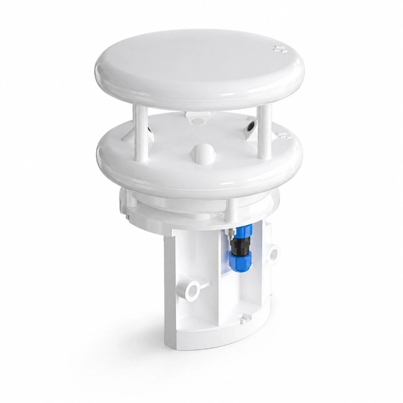
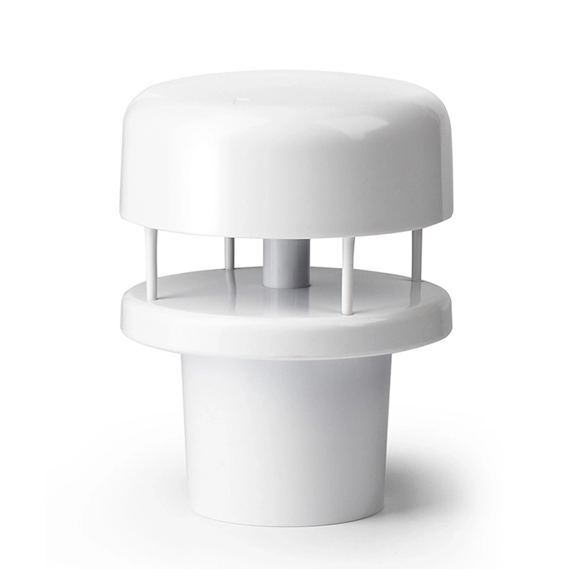
Mechanical Wind Sensor vs Ultrasonic Wind Sensor
Comparison
Mechanical Cup and Vane Sensor
Ultrasonic Wind Sensor
Wind-speed measurement
Rotating cups
Ultrasonic time or phase difference
Wind-direction measurement
Wind vane
Ultrasonic calculation
Mechanical moving parts
Yes
No
Starting threshold
Model-dependent
Usually low
Bearing maintenance
Required periodically
No bearing maintenance
Resistance to dust
Requires inspection
No rotating assembly
Icing risk
Cups and vane may freeze
Transducer area may also ice
Heating option
Model-dependent
Common on selected models
Cost
Often more economical
Often higher
Long-term familiar technology
Yes
Yes
3D wind measurement
No
Available on specialized models
Choose the mechanical sensor when:
The project requires a conventional cup-and-vane structure;
High wind-speed measurement is required;
The project has an established mechanical-sensor maintenance plan;
Cost and familiar field technology are priorities.
Choose an ultrasonic sensor when:
Lower mechanical maintenance is important;
No rotating parts are preferred;
The site has frequent dust-related bearing concerns;
For bankable or certification-related wind-resource campaigns, confirm the required sensor class, calibration certificate, installation standard and measurement uncertainty before selection.
Meteorological Towers
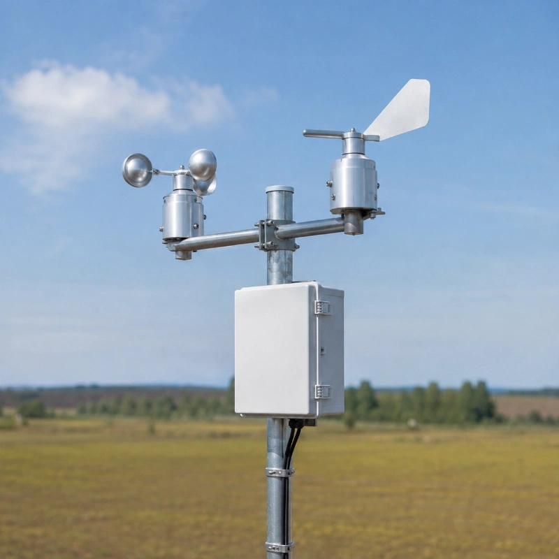
The sensor can be installed on measurement towers at one or more heights.
Multi-height monitoring can help evaluate:
Vertical wind profile
Wind shear
Terrain effects
Height-related wind variation
Each sensor height should be recorded clearly so that data from different levels is not mixed.
Wind Turbine Site Monitoring
The sensor may provide independent meteorological data near turbine locations.
However, data measured on a separate mast, nacelle or ground station may differ because of:
Rotor influence
Nacelle flow distortion
Tower wake
Installation height
Terrain
Sensor distance from the turbine
Solar and Hybrid Renewable-Energy Sites
At hybrid wind and solar projects, wind data can support:
Solar-panel wind-load context
Site weather monitoring
Maintenance safety
Dust-dispersion analysis
Renewable-energy platform integration
Transportation and Infrastructure
The sensor can also be used on:
Bridges
Highways
Ports
Railways
Communication towers
Power transmission towers
For these projects, alarm thresholds should follow the relevant engineering and operational requirements.
Environmental Monitoring
Wind speed and direction can help interpret:
PM concentration
Gas dispersion
Dust transport
Industrial emissions
Odour movement
Air-quality trends
Installation Recommendations
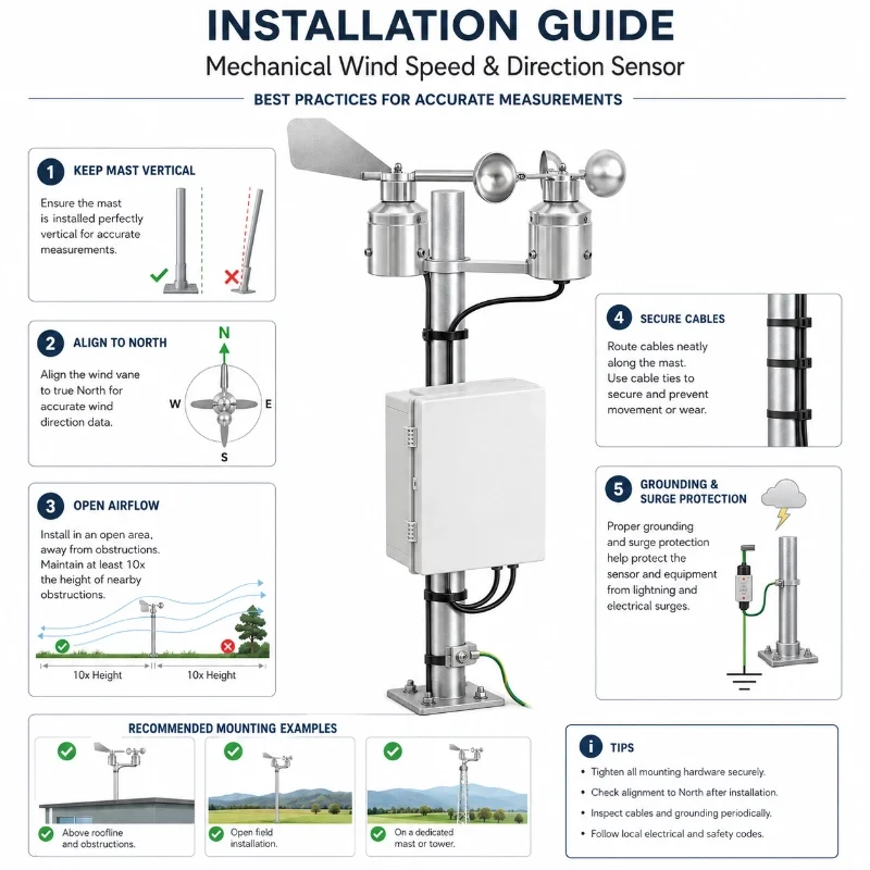
Select an Open and Representative Location
Install the sensor where airflow represents the monitoring objective.
Avoid positions immediately behind:
Buildings
Turbine towers
Solar panels
Trees
Fences
Communication antennas
Large equipment
Other meteorological instruments
These objects may create turbulence or a wind shadow.
Keep the Mast Vertical
The mounting pole and sensor axis should remain vertical.
Tilt can affect:
Wind-cup rotation
Wind-vane alignment
Bearing load
Direction accuracy
Long-term mechanical wear
Align Wind Direction to Geographic North
The wind-direction reference mark should be aligned with true or project-defined north.
Record:
Alignment method
Magnetic declination correction
Installation date
Reference direction
Final offset in the data logger
Incorrect orientation can produce a consistent direction error across the complete dataset.
Use a Suitable Mounting Arm
The mounting arm should:
Keep the sensor away from tower wake;
Minimize flow obstruction;
Remain mechanically stable;
Resist vibration;
Support the expected wind load.
Avoid Cable-Induced Movement
Secure cables so they do not:
Strike the mast;
Pull the sensor;
Interfere with the wind vane;
Vibrate in strong wind;
Damage the connector.
Add Grounding and Surge Protection
Outdoor wind-monitoring towers are exposed to lightning and electrical surges.
Use appropriate:
Shielded cable
Grounding
Surge protection
Lightning protection
Waterproof junction boxes
Cable conduit
Drip loops
The product currently includes multi-layer lightning and electrical-interference protection, but the complete field installation still requires site-level protection design.
Harsh-Environment Installation
Cold and Icing Areas
Freezing rain, frost or snow may affect the movement of the wind cups and vane.
Projects in icing-prone regions should consider:
Heated sensor options
Ice inspection
Camera verification
Heated mounting structures
Low-temperature cable
Suitable power capacity
Maintenance access
Coastal and Offshore Areas
Coastal installations should consider:
Salt spray
Galvanic corrosion
High humidity
Strong wind
Connector sealing
Stainless mounting hardware
Periodic cleaning
Desert and Dusty Areas
Dust may affect bearings and rotating parts.
Recommended measures include:
Routine visual inspection
Bearing-condition checks
Cable-seal inspection
Cleaning according to the maintenance manual
Avoiding unapproved lubricants
High-Wind Sites
For exposed sites:
Confirm the mast and arm strength;
Confirm the maximum sensor rating;
Use reinforced mounting hardware;
Inspect bolts regularly;
Prevent cable vibration;
Configure extreme-wind alarms.
Data Acquisition and Remote Integration
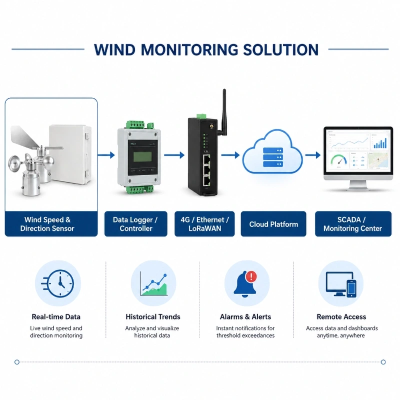
The wind sensor can connect to a data-acquisition instrument or automatic weather station.
A typical architecture is:
Wind Speed and Direction Sensor
→ Wind Data Acquisition Instrument
→ RS485 / Analogue / Project-Configured Interface
→ 4G / Ethernet / LoRaWAN Gateway
→ SCADA, Cloud Platform or Wind Farm Monitoring Center
The monitoring system can provide:
Real-time wind display
Historical curves
Average and maximum values
Wind-direction trends
Wind-rose analysis
Threshold alarms
Device-status monitoring
Data export
API integration
Multi-site comparison
The current product page states that collected data can be transmitted to local terminals, cloud platforms or third-party systems for display, storage, alarm analysis and long-term trend management.
How to Select the Correct Wind Sensor
Before ordering, confirm:
Wind-speed range
Starting threshold
Wind-direction accuracy
Mechanical or ultrasonic measurement
Required averaging period
Maximum gust conditions
Installation height
Mast diameter
Expected temperature range
Icing conditions
Salt-fog or dust exposure
Output signal
Power supply
Data logger model
Communication method
Cable length
Lightning-protection requirement
Calibration requirement
Required documentation
Quantity and OEM requirements
Calibration and Data Quality
For routine environmental monitoring, project-level functional checks may be sufficient.
For professional wind-resource assessment, the project may require:
Traceable calibration
Individual sensor calibration coefficients
Pre-deployment calibration
Post-deployment calibration
Side-by-side comparison
Installation records
Maintenance records
Data-quality flags
Uncertainty analysis
The required procedure depends on the project’s contractual and technical standard.
Maintenance Recommendations
Inspect the following regularly:
Wind cups
Wind vane
Bearings
Mounting bolts
Direction alignment
Cable connector
Housing seal
Corrosion
Ice accumulation
Dust accumulation
Abnormal noise
Rotation resistance
Signal stability
Grounding
Surge protection
Possible warning signs include:
Wind speed remains zero in moving air;
Direction changes are unusually slow;
Data contains repeated jumps;
Mechanical noise increases;
The vane does not return smoothly;
Values differ significantly from nearby sensors.
Request a Wind Monitoring Configuration
Send JW-IoT your wind-energy application, expected wind range, installation height, environmental conditions, output interface and platform requirements.
Our team will help configure a suitable wind speed and direction sensor, data-acquisition instrument and remote monitoring solution.
1. What is this wind speed direction sensor used for?
A
It is used to measure wind speed, wind direction, and environmental parameters in wind farms, weather stations, solar energy fields, transportation systems, environmental monitoring sites, and agricultural applications.
Q
2. What is the wind speed measurement range?
A
The wind speed measurement range is 0 to 75 m/s, with 0.1 m/s resolution. It can measure low wind speeds with a starting threshold below 0.4 m/s.
Q
3. Can this sensor measure wind direction?
A
Yes. The sensor measures wind direction from 0 to 360° with resolution below 1° and typical accuracy of ±2°.
Q
4. Is this sensor suitable for outdoor harsh environments?
A
Yes. The sensor uses aviation grade aluminum, dustproof processing, waterproof sealing, anti corrosion structure, and strong anti interference protection, making it suitable for long term outdoor deployment.
Q
5. Can JW-IoT provide this wind sensor for wind farm monitoring projects?
A
Yes. JW-IoT can provide wind speed and direction sensors for wind farm monitoring, wind resource assessment, tower installation, and complete meteorological monitoring systems.
Q
6. Does the sensor support meteorological station integration?
A
Yes. It can be integrated into automatic weather stations, wind monitoring towers, environmental monitoring systems, and data acquisition platforms.
Q
7. What environmental parameters can the system measure?
A
In addition to wind speed and wind direction, the system can measure air pressure, ambient temperature, and relative humidity depending on the configuration.
Q
8. Why is an imported bearing important for wind measurement?
A
Imported bearings help improve rotation stability, reduce noise, support high speed operation, and extend the service life of the wind measurement sensor.
Q
9. Can JW-IoT customize a wind monitoring solution for solar farms or highways?
A
Yes. JW-IoT can support wind monitoring solutions for solar farms, highways, bridges, industrial parks, and other outdoor environmental monitoring projects.
Q
10. Is the sensor waterproof?
A
Yes. The sensor features IP66 waterproof protection and is designed for outdoor conditions such as rain, dust, humidity, and high wind.
Q
11. What type of data can the system output?
A
The system can output real time wind speed, true wind speed, average wind speed, maximum wind speed, wind direction, true wind direction, synthetic wind speed, wind grade, temperature, humidity, and pressure data.
Q
12. Why choose JW-IoT for wind speed and direction monitoring?
A
JW-IoT provides reliable sensor hardware, project based solution support, data acquisition integration, and overseas application experience for smart meteorology, renewable energy, environmental monitoring, and industrial IoT projects.
 +86 13520127780
  info@jingelway.com