+86 13520127780
  info@jingelway.com








Landslide Monitoring and Geological Hazard Early Warning System
Release time: 2026-07-23
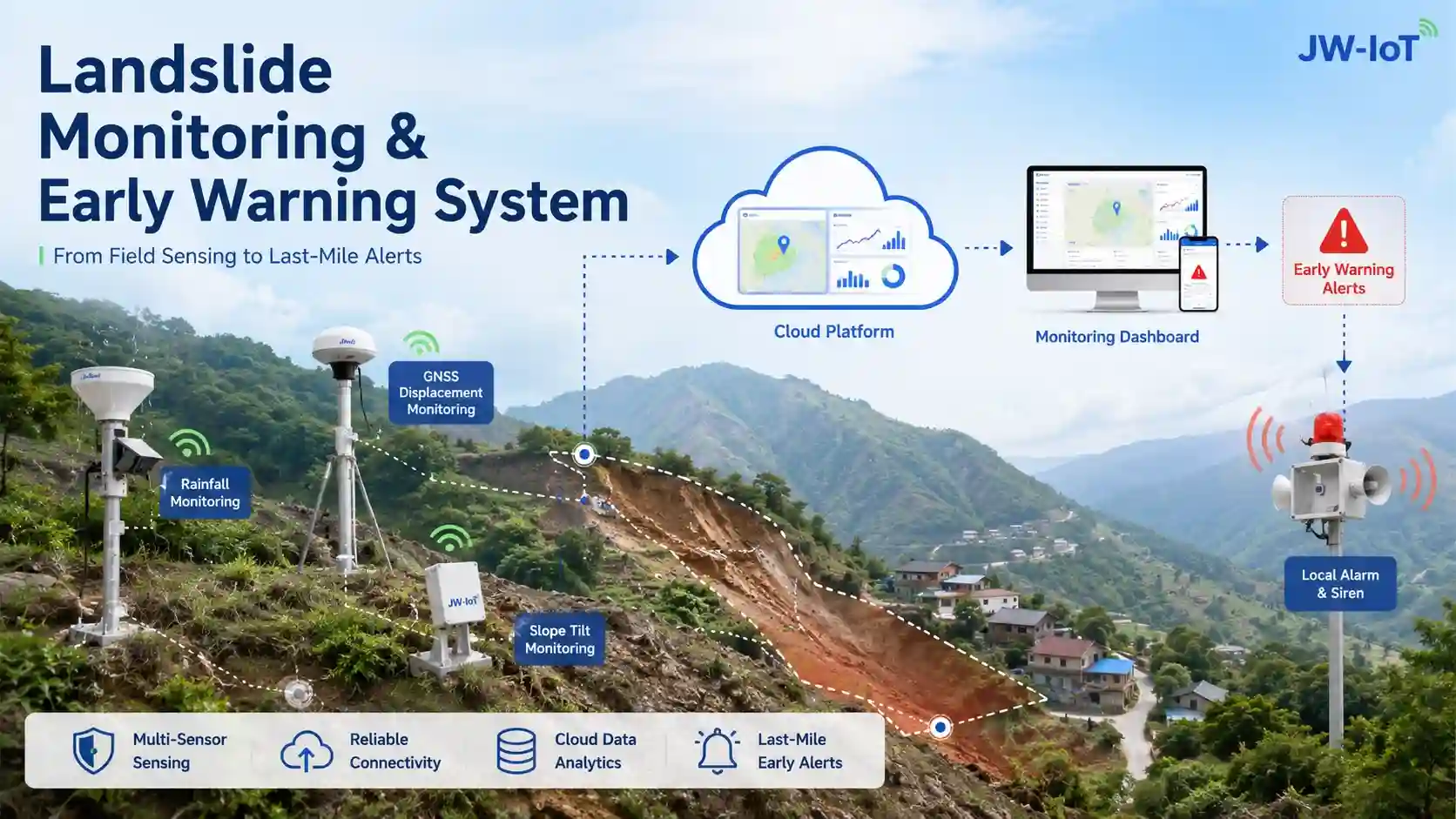
Landslides, debris flows and rainfall-triggered slope failures can develop rapidly, especially in mountainous areas, river valleys, transportation corridors, mining zones and construction sites.
Installing one rainfall sensor or one displacement sensor is not enough to create a reliable warning capability. An effective landslide monitoring system must continuously connect field sensing, data transmission, cloud-based analysis, warning release and emergency response.
A complete geological hazard monitoring and early warning system should therefore answer five practical questions:
- What is happening at the site?
- Is rainfall, deformation or debris movement becoming abnormal?
- Can the data still be transmitted during extreme weather?
- Can warning information reach the people at risk?
- Is there a clear response action after the warning is issued?
This article explains how an IoT-based geological hazard monitoring system can combine rainfall gauges, GNSS receivers, slope tilt sensors, debris-flow detection devices, video monitoring, multi-channel communication, cloud platforms and local alarms to create a closed-loop early warning system.
What Is a Landslide Monitoring System?
A landslide monitoring system is an integrated network designed to observe environmental conditions and ground movement at potential geological hazard sites.
Depending on the project, the system may monitor:
- Real-time rainfall
- Accumulated rainfall
- Rainfall intensity
- Surface displacement
- Horizontal and vertical movement
- Deformation velocity
- Slope inclination
- Ground vibration
- External impact
- Surface cracks
- Debris-flow or mud-level changes
- Wire-break events in debris-flow channels
- On-site images and video
- Equipment and communication status
The system collects data through field sensors, transmits it through wired or wireless communication networks, analyzes it on an IoT platform and activates remote or on-site warning devices when preset conditions are met.
For a complete field solution, explore the JW-IoT Slope Monitoring System, which integrates deformation, rainfall, geological condition, communication, video and early warning functions.
Why Geological Hazard Warning Requires a Complete System
Post-event analyses of flash floods, debris flows and slope disasters repeatedly show that sensor installation alone does not guarantee effective risk reduction.
Typical weaknesses can occur at several stages.
Monitoring Blind Spots
A monitoring station may be online but still fail to capture the most important event.
This can happen when:
- Sensors are installed too far from the hazard source.
- Rainfall stations are not located upstream.
- Station density is insufficient.
- Equipment is aging or poorly maintained.
- Short-duration extreme rainfall is not captured.
- Only one hazard parameter is monitored.
- The selected sensor is unsuitable for strong wind or intense rainfall.
The objective should therefore move beyond a high device online rate toward a high data accuracy rate.
Communication Failure During Extreme Weather
Public cellular networks may become unstable during severe storms, power failures or infrastructure damage.
For remote mountain sites, geological hazard monitoring may require a combination of:
- 4G cellular communication
- LoRaWAN or local wireless networking
- Satellite communication
- Wired RS485 connections
- Local data storage
- Automatic retransmission after network recovery
JW-IoT provides communication devices supporting LoRaWAN, 4G, Ethernet, RS485, MQTT and gateway connectivity for remote monitoring projects.
Warning Information Does Not Reach Everyone at Risk
A platform notification or SMS message is not always sufficient.
Warnings may reach only project managers or local officials, while residents, tourists, workers and temporary construction personnel remain unaware of the danger. Mobile phone coverage may also be limited, and outdoor broadcast sound may not reach every household.
This is often described as the last-mile early warning problem.
A more complete warning strategy can combine:
- Platform notifications
- SMS or mobile alerts
- Local sound and light alarms
- Outdoor high-power warning devices
- Indoor or household alert devices
- Emergency broadcasting
- LED warning displays
- Manual confirmation and follow-up calls
- Local patrol and evacuation procedures
Warning and Response Are Disconnected
A technically correct warning has limited value when the affected organization does not act.
A warning workflow should clearly define:
- Who receives the alert
- Who confirms the alert
- Who performs an on-site inspection
- Who decides whether evacuation is necessary
- Which communities, workers or visitors must move
- Where they should evacuate
- How the response is acknowledged and recorded
The system should support both warning delivery and response confirmation rather than treating the transmission of an alert as the end of the process.
Core Architecture of a Geological Hazard Monitoring System
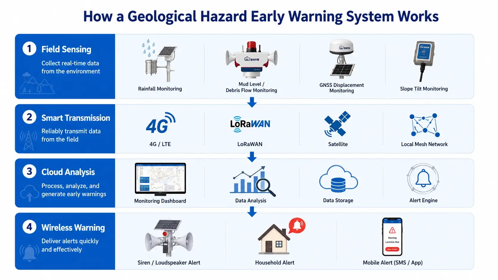
A practical geological hazard early warning system can be divided into five connected layers.
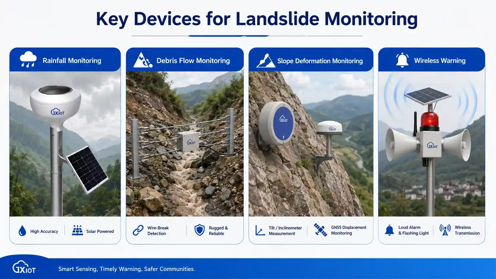
1. Field Sensing Layer
The field sensing layer measures the physical conditions associated with a potential hazard.
Typical devices include:
- Tipping bucket rain gauges
- Piezoelectric rain gauges
- Wind-resistant rain gauges
- GNSS deformation monitoring stations
- Slope tilt probes
- Crack monitoring sensors
- Debris-flow wire-break sensors
- Radar mud-level sensors
- Video monitoring equipment
- Soil and hydrological sensors
2. Edge Data Acquisition Layer
An IoT monitoring terminal or gateway collects sensor readings and performs initial processing.
Depending on the design, the terminal may provide:
- Sensor polling
- Timestamp synchronization
- Threshold comparison
- Local data storage
- Device status monitoring
- Low-power operation
- Solar power management
- Local alarm output
- Protocol conversion
- Remote configuration
3. Communication Layer
The communication layer sends monitoring data from the hazard site to the cloud platform.
Possible communication methods include:
- 4G LTE
- LoRaWAN
- Local self-organizing wireless networks
- BeiDou or other satellite telemetry
- Ethernet
- RS485 Modbus
- MQTT or HTTP API integration
Multi-channel communication is particularly valuable in remote regions where no single network can be assumed to remain available under all conditions.
4. Cloud Analysis and Management Layer
The cloud platform centralizes data from multiple monitoring points and provides:
- Metadata management
- Real-time data visualization
- Historical data storage
- Statistical analysis
- Data exchange
- Data extraction
- Trend analysis
- Warning rule management
- Multi-site mapping
- User and permission management
- Data security
- API-based data sharing
The platform should not analyze one parameter in isolation. Rainfall, displacement, deformation velocity, equipment status and visual evidence should be evaluated together whenever possible.
5. Warning and Emergency Response Layer
When abnormal conditions are detected, warnings can be released through both remote and local channels.
The response layer may include:
- Web platform alerts
- Mobile alerts
- SMS messages
- Email notifications
- Cloud-connected alarms
- Outdoor sound and light alarms
- Indoor warning terminals
- Emergency broadcast systems
- LED displays
- Duty officer assistance
- Manual call confirmation
- On-site patrol and evacuation
The complete data flow can be summarized as:
Sensors → Monitoring Terminal → 4G / LoRaWAN / Satellite Network → Cloud Platform → Multi-Level Warning → Local Response and Evacuation
Rainfall Monitoring for Landslide and Debris-Flow Warning
Rainfall is one of the most important triggering factors in many landslide, flash-flood and debris-flow events.
A rainfall monitoring network should measure more than daily precipitation totals. It should capture:
- Real-time rainfall
- Short-duration rainfall intensity
- Accumulated rainfall
- Continuous rainfall duration
- Rapid changes in rainfall intensity
- Upstream rainfall before water or debris reaches the protected area
JW-IoT offers different types of rain gauges for hydrology, flood warning, weather monitoring and geological hazard projects.
Tipping Bucket Rain Gauges
Tipping bucket rain gauges are widely used because they provide relatively high accuracy at an accessible project cost.
They are suitable for many automatic monitoring networks, but field calibration and maintenance remain important. Under extreme wind and heavy rainfall, conventional designs may experience measurement errors if collection, drainage and bucket stability are not properly addressed.
A project requiring a conventional rainfall sensor can consider the Tipping Bucket Rain Gauge for Weather Monitoring.
Piezoelectric Rain Gauges
A piezoelectric rain gauge calculates rainfall by detecting the impact characteristics of raindrops.
An array-type cantilever sensing structure can estimate rainfall by analyzing factors such as raindrop diameter and impact position. A piezoelectric film design can also reduce power consumption and limit the effects of aging and environmental contamination.
Because this design has no tipping bucket, it can support lower-maintenance deployments in suitable applications.
Wind-Resistant Rain Gauges
Strong wind can affect the amount of rainfall captured by a gauge.
A wind-resistant design may use a steep collection angle, diversion channels, anti-vibration structures and improved drainage geometry to reduce splash and wind-related loss.
The PPT describes a wind-resistant design using a 65-degree large inclination angle, anti-vibration damping and a combination of overturning and diversion channels. It states an accuracy of no more than ±2% across light, medium and heavy rainfall intensities from 0 to 10 mm/min, with measurement repeatability error of no more than ±1%.
Sensor selection should therefore consider not only nominal accuracy but also the rainfall intensity, wind exposure, maintenance conditions and environmental characteristics of the deployment site.
GNSS Deformation Monitoring for Landslide Early Warning
GNSS monitoring stations can detect gradual or accelerating surface movement at landslide-prone slopes.
A GNSS-based system may monitor:
- Horizontal displacement
- Vertical displacement
- Cumulative displacement
- Movement direction
- Deformation velocity
- Changes in movement rate
- Relative movement between multiple monitoring points
The most important indicator is not always the total displacement alone. A rapid increase in deformation velocity may indicate that the slope is entering a more dangerous stage.
Adaptive GNSS Monitoring
The GNSS receiver described in the PPT incorporates a high-precision MEMS sensor to capture station tilt, vibration and external impact.
Based on the detected state, the unit can automatically switch among three operating modes:
- Static sleep
- Dynamic calculation
- Post-processing calculation
This adaptive approach helps reduce power consumption while still capturing the deformation characteristics of the monitored object.
GNSS stations are especially valuable when deployed together with rainfall monitoring, slope inclination sensing, crack inspection and local warning devices.
Slope Tilt Probes and MEMS Deformation Monitoring
A slope tilt probe is an integrated IoT sensor used to monitor factors associated with surface deformation.
Depending on the configuration, it can measure:
- Three-axis inclination
- Combined inclination
- Azimuth
- Three-axis acceleration
- Vibration
- External impact
The PPT describes the slope probe as a highly integrated, low-power device that can work with smart gateways, GNSS deformation measurement, warning equipment and an IoT platform.
Together, these components create a self-powered and closed-loop system capable of:
- Automatic monitoring
- Local data collection
- Automated analysis
- Threshold identification
- Remote warning
- On-site alarming
This type of device can be installed at slopes, retaining structures, crack zones, road cuts, mine slopes and other locations where changes in surface orientation may indicate instability.
Debris-Flow Wire-Break Monitoring
A debris-flow wire-break sensor provides a simple and direct way to detect the passage of destructive material through a channel.
A steel wire is installed across the debris-flow gully. When a debris flow occurs, the moving material breaks the wire and changes the sensor’s switch output, triggering an alarm.
The PPT specifies the following parameters for the described device:
- Main body material: aluminum alloy
- Tensile resistance: at least 200 N
- Protection rating: IP67
- Output interface: switch signal
Wire-break sensors can be deployed near check dams or in untreated channels.
Their primary advantage is event confirmation. However, they should not normally be used as the only monitoring method because the warning may be generated only after the debris flow has reached the installation point.
For more complete protection, wire-break monitoring should be combined with upstream rainfall stations, mud-level sensing, cameras, communication terminals and downstream warning devices.
Video Monitoring and Visual Verification
Sensor data shows that a condition is changing, while video helps operators understand what is physically happening at the site.
Intelligent video equipment can support:
- Real-time visual inspection
- Crack and surface condition observation
- Verification of debris or water movement
- Monitoring of roads and evacuation routes
- Confirmation of equipment condition
- Post-event review
For remote sites, video should be triggered or sampled intelligently to balance situational awareness with power and communication bandwidth.
A multi-element monitoring station may also integrate meteorological sensing, rainfall monitoring, high-definition panoramic video, solar power, LED data display and multi-channel 4G plus satellite communication.
Local Wireless Networking and Satellite Telemetry
Mountainous hazard sites often have difficult terrain and unreliable cellular coverage.
Two important alternatives are local wireless networking and satellite telemetry.
Local Self-Organizing Networks
A local wireless network can connect multiple sensors and warning devices within the monitored area.
It can help link:
- Rainfall monitoring points
- GNSS stations
- Tilt sensors
- Debris-flow sensors
- Local alarms
- Gateways
- Household warning devices
Local networking can allow on-site alarm linkage even when the external public network is unavailable.
Satellite Communication
Satellite telemetry can provide a backup or primary transmission route for remote geological hazard sites.
It is especially relevant when:
- Cellular coverage is unavailable.
- Extreme weather may damage terrestrial networks.
- Monitoring points are distributed across large mountain regions.
- Warning information must reach a central platform reliably.
- Communication redundancy is required.
The choice between 4G, LoRaWAN, satellite communication and wired connections should be based on terrain, station density, power availability, data volume, coverage and emergency response requirements.
How Multi-Level Warning Rules Should Work
A geological hazard platform can use multi-level thresholds rather than a single alarm point.
A typical warning structure may include:
- Blue warning: initial abnormal change
- Yellow warning: continued development or threshold exceedance
- Orange warning: significant acceleration or combined risk
- Red warning: high risk requiring immediate action
Warning levels can be based on:
- Cumulative rainfall
- Short-duration rainfall intensity
- Cumulative displacement
- Deformation velocity
- Sudden tilt changes
- Wire-break status
- Mud-level threshold
- Multiple parameters occurring together
- Manual inspection results
The threshold values must be configured for the specific site. Geological conditions, historical movement, slope structure, rainfall patterns and the location of threatened people or infrastructure all affect how warning rules should be set.
Real Landslide Warning Case: Monitoring Enabled Early Evacuation
A monitoring project was installed at the Shiyanjiao landslide site in Jianxing Village, Xinping County, Yuxi City, in April 2021.
The deployed equipment included:
- One rainfall monitoring station
- Seven GNSS monitoring stations
- One sound and light alarm
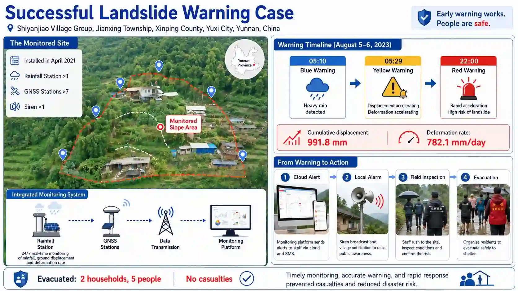
During a monitoring period in August 2023, the GNSS01 surface displacement station detected a continuous increase in horizontal displacement and deformation velocity.
The recorded cumulative displacement reached 991.8 mm, while the horizontal deformation velocity reached 782.1 mm per day.
The system successively triggered yellow, orange and red warnings. The local warning broadcast was activated, and the platform sent messages to technical personnel and disaster-prevention personnel.
The monitoring team increased the frequency of field inspections. The inspection found clear signs of slope movement:
- Multiple cracks in the front, middle and rear parts of the slope
- A maximum crack length of approximately 16 meters
- A maximum crack width of approximately 30 centimeters
- A visible crack depth of approximately 40 centimeters
- A maximum scarp height of approximately 40 centimeters in the seriously deformed front area
Two households with five people located in the directly threatened area were evacuated in time. No casualties occurred.
This case demonstrates that successful landslide warning depends on more than detecting displacement. The effective chain included:
- Continuous GNSS monitoring
- Detection of accelerating deformation
- Multi-level platform warnings
- Immediate local broadcast
- Notification of responsible personnel
- Confirmation by the duty team
- Increased field inspection
- Identification of visible cracks
- Evacuation of threatened residents
The system worked because monitoring, warning, confirmation and action formed a complete closed loop.
How to Design a Geological Hazard Monitoring Project
Every site requires a specific monitoring design. A practical planning process can include the following steps.
Step 1: Identify the Hazard Mechanism
Determine whether the main risk is related to:
- Rainfall-triggered landslide
- Debris flow
- Rockfall
- Surface deformation
- Deep slope movement
- River blockage
- Construction disturbance
- Mining activity
- Reservoir water-level change
Step 2: Identify Threatened Objects
Map the people and assets exposed to the hazard, such as:
- Villages
- Individual households
- Schools
- Tourist areas
- Construction camps
- Mines
- Highways
- Railways
- Bridges
- Pipelines
- Reservoir facilities
- Transmission lines
Step 3: Select Monitoring Parameters
Choose sensors according to the hazard mechanism rather than selecting devices only by product availability.
For example:
- Rainfall-triggered slope: rainfall gauge, GNSS, tilt and soil or hydrological sensing
- Debris-flow gully: upstream rainfall, wire-break sensor, radar mud-level sensor and camera
- Highway slope: GNSS, crack sensor, tilt probe, rainfall gauge, video and local alarms
- Remote mountain site: low-power sensors, solar power, 4G plus satellite backup
- Populated area: platform notifications, outdoor alarms and household warning devices
Step 4: Remove Monitoring Blind Spots
Monitoring points should cover:
- Hazard source areas
- Upstream rainfall zones
- Active cracks
- Slope surface movement zones
- Potential debris-flow channels
- Retaining structures
- Downstream communities
- Evacuation roads
- Communication relay positions
Step 5: Design Communication Redundancy
Do not assume that a public cellular network will always remain available.
Evaluate:
- Cellular signal quality
- Local wireless coverage
- Satellite backup
- Offline storage
- Local alarm linkage
- Solar power autonomy
- Equipment health monitoring
Step 6: Establish Warning Responsibilities
The emergency workflow should specify:
- Warning recipients
- Responsible decision-makers
- Duty personnel
- Field inspectors
- Community contacts
- Evacuation coordinators
- Acknowledgment requirements
- Escalation procedures
Step 7: Test the Entire Warning Chain
A project acceptance test should not stop after confirming that data appears on the cloud dashboard.
The test should verify:
- Sensor response
- Data accuracy
- Gateway communication
- Offline storage
- Network recovery
- Threshold activation
- Platform notification
- Local alarm activation
- Broadcast audibility
- Household notification
- User acknowledgment
- Emergency contact workflow
Common Mistakes in Landslide Monitoring Projects
Relying on One Sensor
Landslide risk is usually influenced by multiple factors. A rainfall gauge alone cannot confirm slope movement, while a displacement sensor alone may not explain the triggering conditions.
Measuring Only at the Threatened Location
Upstream rainfall and hazard-source monitoring may provide more warning time than sensors installed only near the community.
Focusing Only on Device Online Rate
An online device may still produce inaccurate or unrepresentative data. Calibration, placement and environmental suitability remain essential.
Depending Only on SMS
SMS messages can be delayed, ignored or delivered only to a limited group. Local sound, light, broadcast and household warning methods may also be required.
Ignoring Temporary Populations
Tourists, migrant workers, construction teams and visitors may not be included in local contact lists but can still be highly exposed.
Failing to Define Evacuation Actions
Warnings should contain clear instructions. A vague risk notification is less effective than a defined action message with an evacuation route and responsible coordinator.
Using a Single Communication Channel
Extreme weather is precisely when cellular and power infrastructure may fail. Communication and power redundancy should be considered during system design.
Applications of Geological Hazard Monitoring Systems
A landslide and geological hazard early warning system can be used for:
- Landslide-prone villages
- Debris-flow gullies
- Mountain highways
- Railways and bridge approaches
- Open-pit mines
- Underground mine entrances
- Construction camps
- Hydropower projects
- Reservoir slopes
- Dam abutments
- Transmission line corridors
- Oil and gas pipelines
- Tourist areas
- Mountain schools
- Municipal geological hazard networks
JW-IoT’s Industrial IoT Monitoring solutions include slope monitoring and structural safety applications for remote and harsh field environments.
Building a Sensor-to-Response Geological Hazard Solution
The performance of a landslide early warning project should not be evaluated only by the number of sensors installed.
A successful system must connect:
- Accurate field sensing
- Reliable power supply
- Redundant communication
- Cloud-based analysis
- Multi-level warning rules
- Local alarm devices
- Responsible personnel
- Field verification
- Evacuation action
The most important objective is not simply to collect data. It is to convert changes in rainfall, displacement, tilt and debris movement into an understandable warning and a timely protective action.
JW-IoT supports project-based integration for geological hazard, slope safety, hydrology and remote environmental monitoring applications. Solutions can include field sensors, IoT data terminals, LoRaWAN or 4G gateways, cloud platform integration, local sound and light alarms and API connectivity.
Contact JW-IoT to discuss your monitoring parameters, site conditions, communication requirements and early warning workflow.
Frequently Asked Questions
What sensors are used in a landslide monitoring system?
Common devices include rainfall gauges, GNSS displacement stations, tilt sensors, crack sensors, soil and hydrological sensors, radar mud-level sensors, debris-flow wire-break sensors and video cameras.
Why is rainfall monitored for landslide warning?
Heavy rainfall and short-duration intense rainfall can trigger soil saturation, runoff, erosion, slope deformation, flash floods and debris flows. Upstream rainfall monitoring can also provide additional warning time.
Can GNSS detect a landslide before failure?
GNSS can detect surface displacement and changes in deformation velocity. It is particularly useful when movement becomes continuous or begins to accelerate. GNSS data should be combined with rainfall, field inspection and other deformation measurements.
What is a debris-flow wire-break sensor?
A wire-break sensor uses a steel wire installed across a debris-flow channel. When moving debris breaks the wire, the sensor changes its switch output and triggers an alarm.
How is data transmitted from remote mountain sites?
Depending on site conditions, systems can use 4G LTE, LoRaWAN, local self-organizing wireless networks, satellite telemetry, RS485 or a combination of several channels.
What happens when the cellular network fails?
A resilient system may store data locally, use satellite or local wireless backup and activate on-site warning devices without relying entirely on the external public network.
Why are local warning devices necessary?
SMS and cloud notifications may not reach residents, workers or tourists in time. Outdoor alarms, indoor warning devices, broadcasts and LED displays help deliver warnings directly to people in the affected area.
Can the system use multi-level warnings?
Yes. A platform can issue blue, yellow, orange and red warnings based on rainfall, displacement, deformation velocity, tilt, debris-flow detection or combinations of several parameters.
Does JW-IoT support platform and API integration?
JW-IoT solutions can support sensor-to-cloud architecture, communication gateways, monitoring dashboards and MQTT or API-based integration according to project requirements.