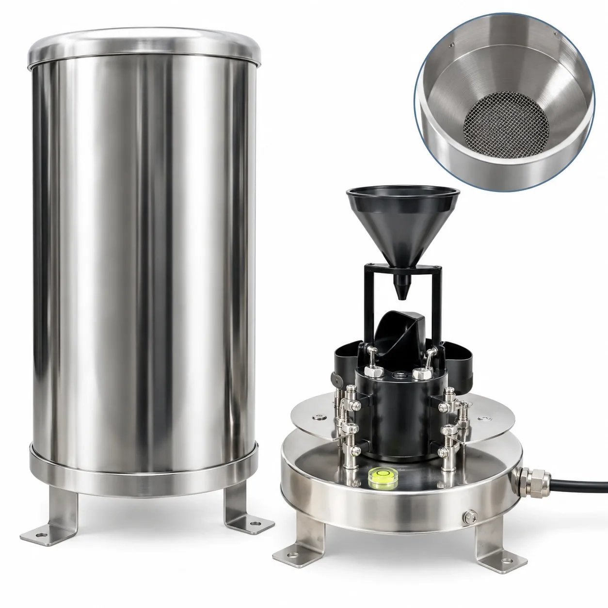
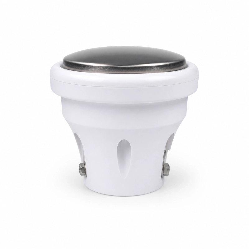
Optical Rain Gauge Sensor for Flood Warning Monitoring
Key Features
Optical Rainfall Measurement: Uses optical sensing technology to detect rainfall intensity without relying on a traditional tipping bucket mechanism.
High Resolution Output: Standard 0.1 mm rainfall resolution supports precise rainfall data collection for weather and hydrology applications.
Fast Response for Real Time Monitoring: Optical detection enables rapid rainfall response, helping improve flood warning and short duration rainfall tracking.
RS485 and Pulse Output Options: Supports RS485 output and pulse output for integration with data loggers, RTUs, PLCs and IoT monitoring systems.
Modbus RTU Communication
Compatible with common industrial monitoring platforms through Modbus RTU protocol.
Low Power Consumption: Power consumption is less than 0.24 W, suitable for solar powered and battery assisted outdoor stations.
Wide Working Environment: Operates from -40°C to 60°C and 0 to 100% RH, suitable for harsh outdoor weather conditions.
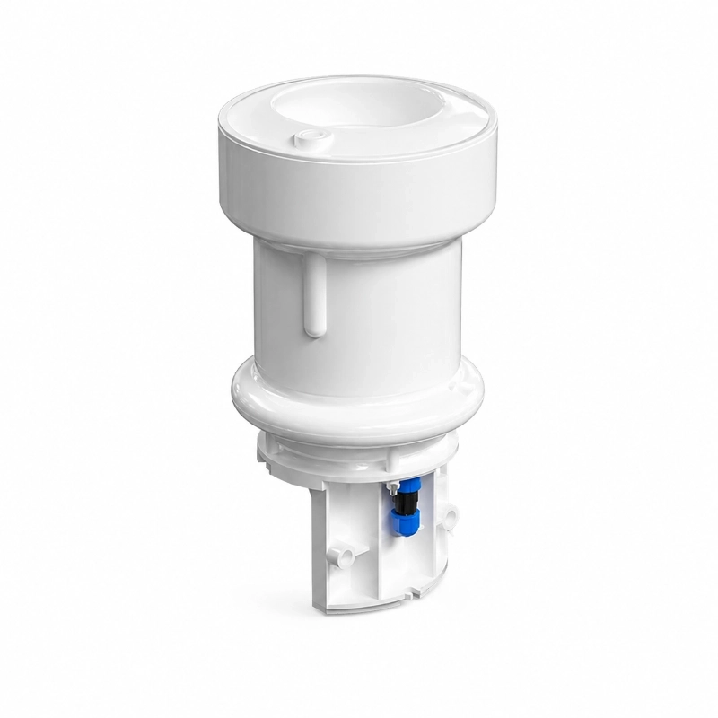
Compact and Easy to Install: Small size, simple structure and lightweight design make it easy to integrate into rainfall stations or multi parameter weather stations.
Stable Performance with Low Maintenance: Optical structure reduces mechanical movement, helping lower maintenance requirements compared with mechanical rain gauges.
Customizable Multi Parameter Integration: Can be integrated with wind speed, wind direction, temperature, humidity, pressure and other environmental sensors for complete weather monitoring systems.
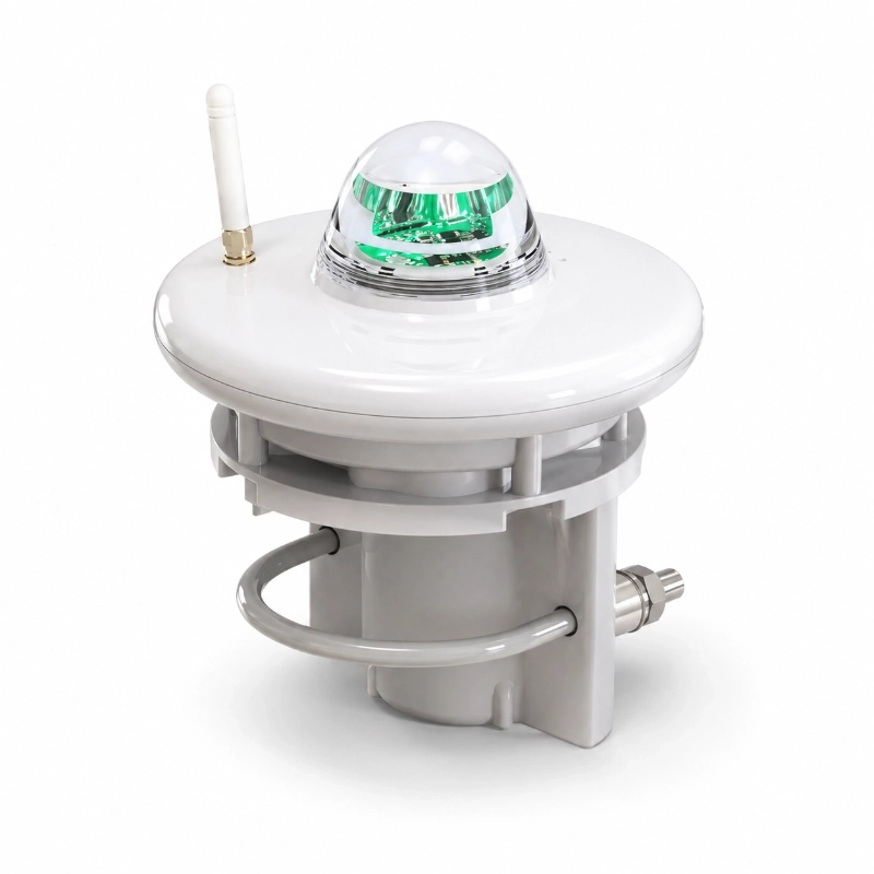
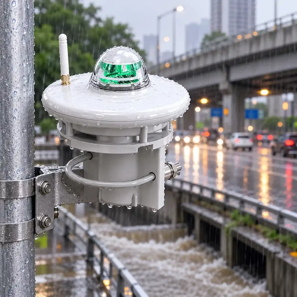
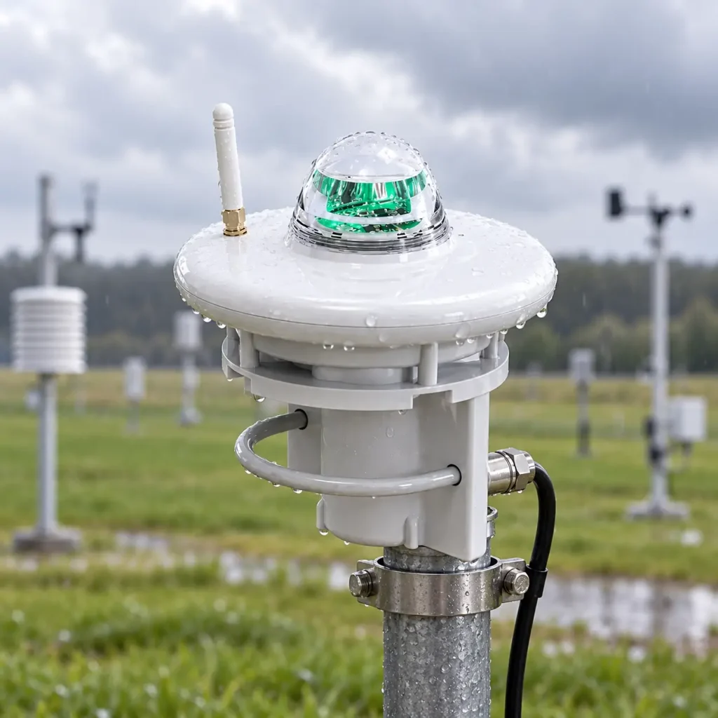
JW-RG-GYL1(LC42) Optical Rain Gauge Sensor is designed for real-time rainfall detection in flood warning, hydrological monitoring, automatic weather stations, urban waterlogging monitoring and environmental IoT systems.
Unlike a conventional tipping bucket rain gauge, this sensor uses optical sensing technology to detect rainfall without relying on a mechanical tipping mechanism. Multiple optical sensing elements detect raindrop conditions and convert them into rainfall information for continuous monitoring.
With 0.1 mm standard resolution, RS485 Modbus RTU or pulse output, low power consumption and a compact structure, the sensor can be integrated into remote monitoring stations, hydrological RTUs, weather station data loggers and IoT gateways.
It is particularly suitable for projects that require:
Integration with flood warning or environmental IoT systems
Fast rainfall response
Continuous outdoor precipitation monitoring
Digital RS485 communication
Low-power field deployment
Reduced mechanical maintenance
1. Product Description
The JW-RG-GYL1(LC42) Optical Rain Gauge Sensor is developed for automated rainfall monitoring where rapid response, digital output and compact installation are important.
The sensor uses optical elements to detect rainfall conditions, including raindrop density and falling characteristics, and processes the detected information to provide rainfall measurement data.
Compared with a conventional tipping bucket rain gauge, the optical measuring approach does not require rainwater to fill and tip a mechanical bucket before producing a measurement signal.
This makes the sensor suitable for applications requiring continuous rainfall observation and rapid detection of changing precipitation conditions.
Typical projects include:
Flood early warning
Mountain flood monitoring
Urban waterlogging monitoring
Automatic weather stations
Hydrological observation
Reservoir and river monitoring
Agricultural weather monitoring
Environmental IoT systems
For larger flood and disaster prevention projects, rainfall data can also be combined with water-level sensors, RTUs, communication equipment and warning devices through a complete Flood Monitoring System.
2. How Does an Optical Rain Gauge Work?
An optical rain gauge measures rainfall using optical sensing rather than a mechanical tipping bucket.
When raindrops pass through the sensor’s detection area, the optical sensing elements detect changes caused by the falling droplets.
These detected signals are processed to determine rainfall information.
The JW-RG-GYL1(LC42) uses multiple optical probes to support rainfall detection.
In practical monitoring systems, the resulting rainfall data can then be transmitted through:
Optical Rain Gauge → RS485 / Pulse Output → Data Logger / RTU → Communication Network → Monitoring Platform
This architecture allows the rainfall sensor to become part of a larger automated environmental monitoring system.
3. Optical Rain Gauge vs. Tipping Bucket Rain Gauge
Optical and tipping bucket rain gauges can both be used for rainfall monitoring, but they use different measurement principles.
Optical Rain Gauge
An optical rain gauge detects rainfall using optical sensing elements.
Typical characteristics include:
No traditional tipping bucket mechanism
Rapid rainfall response
Compact structure
Digital system integration
Low mechanical wear
Suitable for distributed or remote monitoring
For this model, output options include RS485 Modbus RTU and pulse signals.
Tipping Bucket Rain Gauge
A tipping bucket rain gauge collects rainwater through a funnel.
When a calibrated bucket fills to a specified amount, the bucket tips and produces an electrical pulse.
Each tip represents a defined amount of rainfall.
This measurement method is widely used in meteorological and hydrological monitoring.
Which Type Should You Choose?
The appropriate rain gauge depends on the project requirements.
An optical rain gauge may be suitable when the project prioritizes:
Fast rainfall response
Compact installation
Reduced mechanical movement
RS485 digital integration
Low-power operation
Distributed IoT monitoring
A tipping bucket rain gauge may be more appropriate when the project specification explicitly requires tipping bucket measurement.
Sensor selection should always consider the required:
Measurement principle
Resolution
Output interface
Communication protocol
Installation environment
System architecture
4. Technical Specifications
Item
Specification
Product Type
Optical Rain Gauge Sensor
Rain Sensing Diameter
6 cm
Measuring Range
0 to 30 mm per minute
Power Supply
9 to 30V DC
Power Consumption
Less than 0.24 W
Resolution
Standard 0.1 mm
Typical Accuracy
±5%
Output Options
RS485 output or pulse output
Communication Protocol
Modbus RTU
Working Temperature
-40°C to 60°C
Working Humidity
0 to 100% RH
Baud Rate
Default 9600 adjustable
Default Communication Address
01 adjustable
Approximate Size
Diameter 150 mm
Approximate Height
173.5 mm
5. RS485 Modbus RTU Integration
The JW-RG-GYL1(LC42) supports RS485 communication using Modbus RTU protocol.
This makes it suitable for integration with common industrial and environmental monitoring equipment.
Compatible equipment may include:
Weather station data loggers
Hydrological RTUs
PLC systems
IoT gateways
Environmental monitoring terminals
Remote telemetry units
The default communication settings are:
Baud rate: 9600
Communication address: 01
Both can be adjusted according to system requirements.
A typical system architecture may be:
Optical Rain Gauge ↓ RS485 Modbus RTU ↓ Data Logger / RTU ↓ 4G / LoRaWAN / Ethernet / Other Gateway ↓ Cloud Platform or SCADA
The communication method used beyond the rain gauge depends on the selected RTU, data logger or gateway.
6. Pulse Output Integration
In addition to RS485, the sensor can also support pulse output.
Pulse output can be useful when the monitoring equipment is designed to receive pulse signals rather than Modbus data.
Typical receiving devices may include:
Rainfall data loggers
PLC input modules
Remote telemetry terminals
Dedicated rainfall monitoring controllers
Before installation, the system integrator should confirm whether the project requires:
RS485 Modbus RTU
Pulse output
This avoids interface compatibility problems during commissioning.
7. Optical Rain Gauge for Flood Early Warning
Rainfall is one of the key environmental parameters in flood-related monitoring systems.
Heavy or rapidly changing rainfall can be monitored together with changes in:
River level
Reservoir level
Drainage depth
Road flooding depth
Channel water level
The optical rain gauge provides rainfall information to the monitoring system.
A typical flood monitoring architecture may be:
Optical Rain Gauge + Water Level Sensor ↓ RTU / Data Logger ↓ 4G / Wireless Communication ↓ Flood Monitoring Platform ↓ Alarm / Warning Function
For more complete systems, additional components may include:
Cameras
Warning lights
Sirens
LED displays
Solar power systems
Remote communication modules
The rain gauge itself measures rainfall. Flood warning decisions depend on the complete system architecture, configured thresholds and monitoring strategy.
The optical rain gauge can provide continuous rainfall data for flood monitoring stations.
It can be used in projects involving:
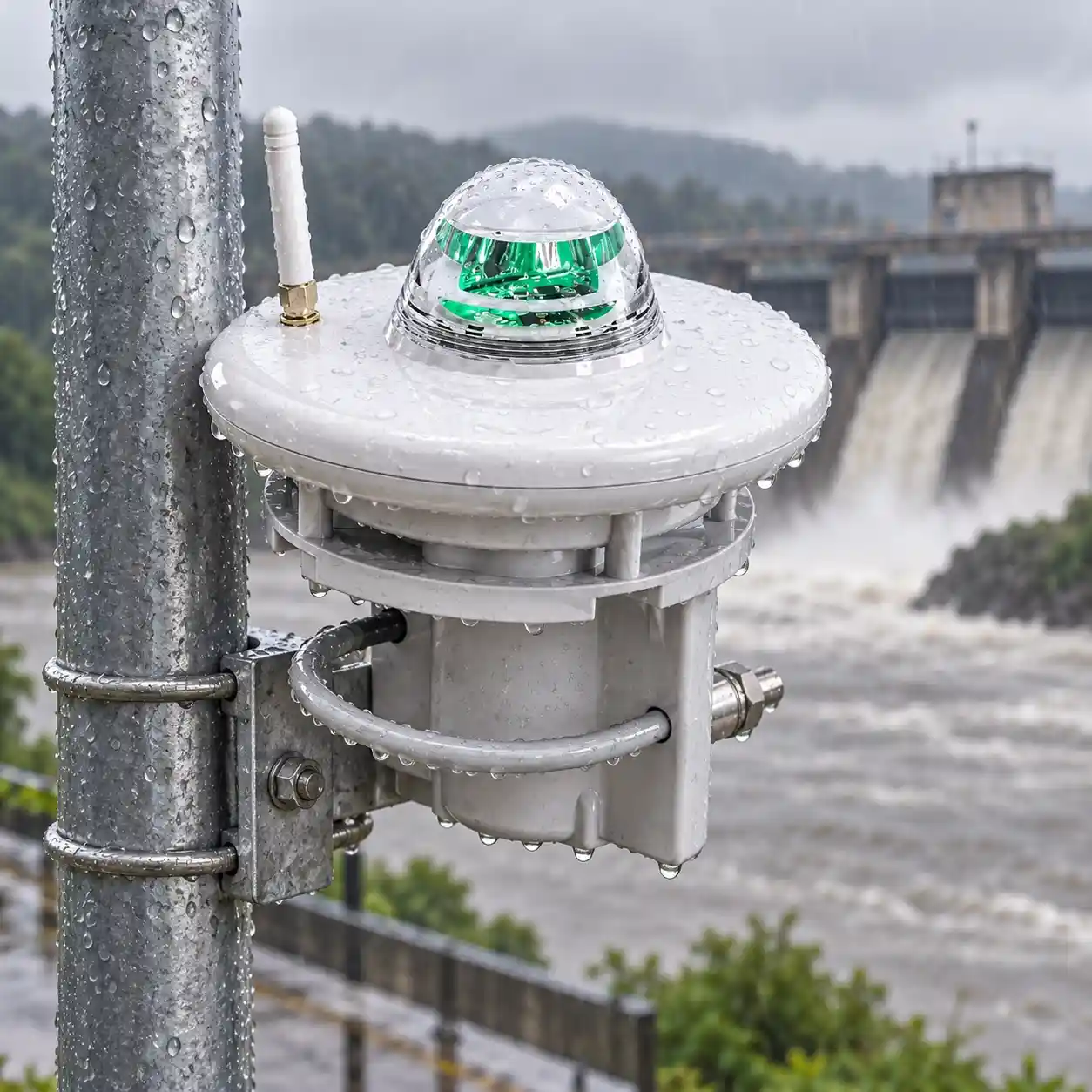
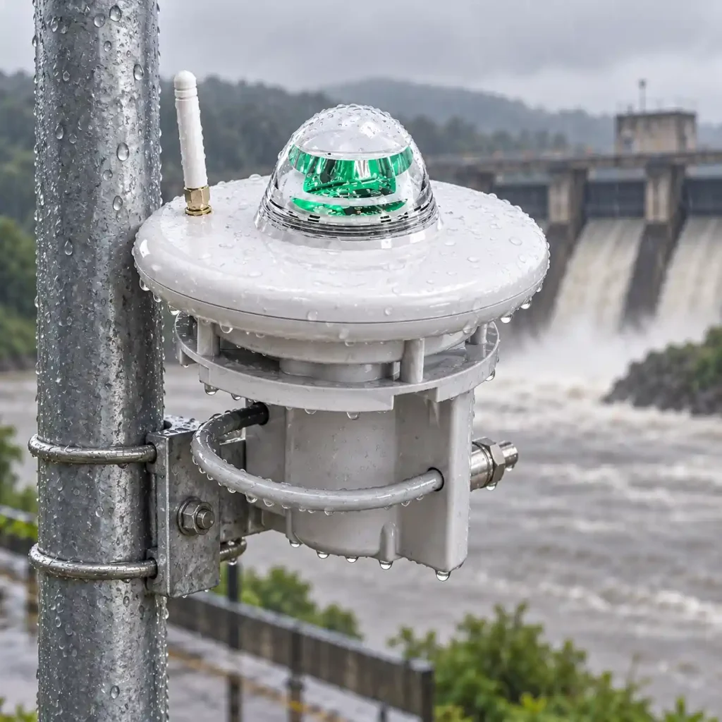
River flood monitoring
Mountain flood monitoring
Watershed rainfall monitoring
Reservoir catchment monitoring
Rural flood warning
Disaster prevention systems
When combined with water-level sensors and communication equipment, rainfall data can support a broader flood monitoring network.
8.2 Mountain Torrent Monitoring
Mountainous regions can experience rapid rainfall changes over relatively small areas.
Distributed rainfall sensors can be installed at multiple monitoring points to collect local precipitation data.
A typical mountain monitoring station may include:
Optical rain gauge
Water-level sensor
RTU
Solar power supply
Wireless communication equipment
The collected data can then be transmitted to a central monitoring platform.
8.3 Urban Waterlogging Monitoring
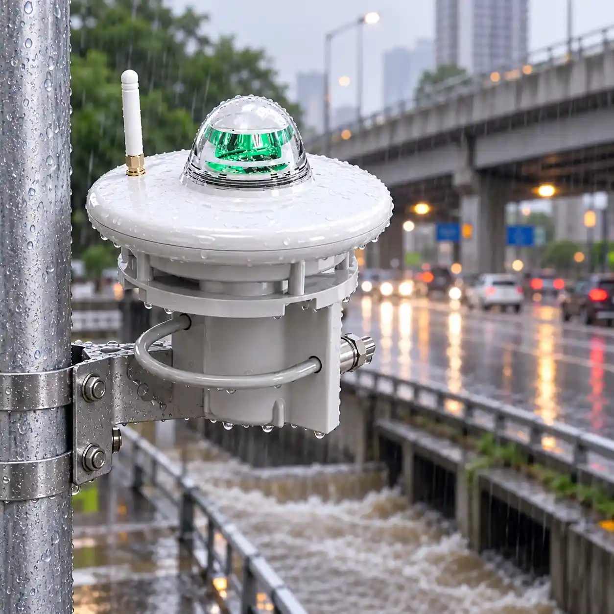
Urban drainage systems can be affected by short-duration rainfall events.
An optical rain gauge can be installed at:
Road intersections
Underpasses
Drainage catchments
Urban monitoring stations
Flood-prone locations
Rainfall information can be combined with water-depth or water-level measurements to provide a more complete picture of urban waterlogging conditions.
A typical urban system may combine:
Rainfall + Road Water Depth + Drainage Water Level + Remote Communication
This information can support city drainage monitoring and emergency response platforms.
8.4 Automatic Weather Stations
The sensor can be integrated into automatic weather monitoring systems together with:
Wind speed
Wind direction
Air temperature
Relative humidity
Atmospheric pressure
This enables rainfall to be monitored together with other meteorological parameters.
A complete system can send weather data to a local controller or remote monitoring platform.
The compact sensor structure makes it suitable for both standalone rainfall stations and multi-parameter weather monitoring stations.
8.5 Hydrology and Water Conservancy Monitoring
Rainfall measurement is widely used in hydrological monitoring because precipitation directly influences catchment runoff and water-level conditions.
The optical rain gauge can be used at:
Rivers
Reservoirs
Irrigation districts
Watersheds
Water conservancy facilities
Hydrological stations
Rainfall data can be integrated with:
Water level
Flow
Gate status
Remote telemetry
This creates a broader water conservancy monitoring system.
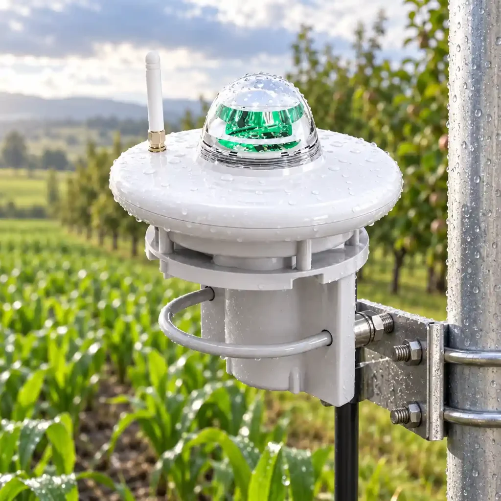
8.6 Smart Agriculture
Rainfall is an important environmental parameter for outdoor agricultural monitoring.
The sensor can be deployed in:
Crop fields
Orchards
Irrigation districts
Agricultural research stations
Farm weather monitoring networks
It can be combined with:
Soil moisture sensors
Air temperature sensors
Humidity sensors
Solar radiation sensors
Wind sensors
This allows rainfall information to become part of a complete agricultural weather monitoring system.
8.7 Environmental IoT Monitoring
The RS485 interface makes the optical rain gauge suitable for distributed IoT monitoring networks.
Possible applications include:
Environmental monitoring stations
Smart city infrastructure
Remote telemetry systems
Disaster prevention stations
Distributed weather monitoring
Multiple environmental sensors can be connected to compatible RTUs or IoT gateways and transmitted to a centralized monitoring platform.
9. Low-Power Remote Rainfall Monitoring
Many rainfall monitoring stations are installed in locations without permanent grid power.
Examples include:
Mountain areas
River basins
Reservoirs
Agricultural fields
Remote weather stations
The sensor consumes less than 0.24 W, making it suitable for consideration in low-power monitoring systems.
A remote station may include:
Optical rain gauge
Data logger or RTU
Communication gateway
Battery
Solar power system
The power system should be designed according to the total power consumption of all connected devices.
The rain gauge’s low power consumption alone does not determine the required solar panel or battery capacity.
10. Installation and System Design Considerations
Correct installation is important for reliable rainfall monitoring.
When selecting an installation point, system designers should consider the following factors.
Keep the Detection Area Unobstructed
Avoid placing the rain gauge directly under:
Roof edges
Trees
Large structures
Other equipment that may block rainfall
The sensor should have appropriate exposure to falling precipitation.
Use a Stable Mounting Structure
The mounting pole or bracket should be mechanically stable.
Unnecessary movement or vibration should be minimized.
Confirm Output Before Installation
Before wiring, confirm whether the selected model uses:
RS485
Pulse output
For RS485 systems, confirm:
Power supply
A/B communication wiring
Baud rate
Communication address
Protect Cables
Outdoor communication cables should be routed securely to reduce the risk of:
Mechanical damage
Loose connections
Excessive cable movement
Consider the Complete Monitoring System
The rainfall sensor is only one part of a field station.
Project design should also consider:
Power supply
RTU or data logger
Communication network
Cloud platform
Alarm strategy
Maintenance access
11. Recommended System Configurations
Flood Monitoring Station
Optical Rain Gauge
Water Level Sensor
RTU
4G / Wireless Communication
Cloud Monitoring Platform
Suitable for rivers, mountain catchments and flood-prone areas.
Urban Waterlogging Station
Optical Rain Gauge
Road Water Depth Sensor
Drainage Water Level Sensor
RTU / IoT Gateway
Remote Monitoring Platform
Suitable for underpasses, roads and urban drainage locations.
Automatic Weather Station
Optical Rain Gauge
Wind Speed & Direction
Temperature & Humidity
Pressure Sensor
Data Logger
Suitable for meteorological, agricultural and environmental monitoring.
Remote Hydrological Station
Optical Rain Gauge
Water Level Sensor
Solar Power
Remote RTU
Wireless Communication
Suitable for rivers, reservoirs and remote water conservancy monitoring.
12. How to Select an Optical Rain Gauge for Your Project
Before choosing a rainfall sensor, confirm the following requirements.
Measuring Range
JW-RG-GYL1(LC42) provides a measuring range of:
0–30 mm/min
Confirm that this is suitable for the target application.
Resolution
The standard resolution is:
0.1 mm
Accuracy Requirement
The listed typical accuracy is:
±5%
If a project specification requires a particular accuracy or meteorological standard, confirm compatibility before procurement.
Communication Interface
Choose between:
RS485
Pulse output
RS485 Protocol
The RS485 version supports:
Modbus RTU
Power Supply
Required power supply:
9–30V DC
Operating Environment
The listed working environment is:
-40°C to 60°C
0–100% RH
System Integration
Confirm what equipment the sensor will connect to:
PLC
RTU
Weather station controller
IoT gateway
Data logger
Providing this information during selection can help avoid integration problems.
13. Optical Rain Gauge vs. Piezoelectric Rain Gauge
Both optical and piezoelectric rain gauges avoid the traditional mechanical tipping bucket mechanism, but they use different sensing principles.
Optical Rain Gauge
Detects rainfall through optical sensing elements.
This model provides:
0–30 mm/min range
0.1 mm resolution
RS485 or pulse output
Modbus RTU on RS485 version
Piezoelectric Rain Gauge
A piezoelectric rain gauge detects the physical impact of raindrops on a sensing surface.
The appropriate choice depends on:
Required measurement principle
Project specifications
Output requirements
Monitoring environment
Integration architecture
For projects comparing different rainfall sensor technologies, it is useful to evaluate the complete monitoring system rather than selecting solely by sensor type.
14. Build Your Rainfall Monitoring System with JW-IoT
A rainfall monitoring project often requires more than one sensor.
Depending on the application, a complete system may include:
Optical rain gauge
Water-level sensor
Weather sensors
RTU or data logger
IoT gateway
Wireless communication
Solar power system
Monitoring platform
JW-IoT provides sensing and IoT monitoring equipment for meteorology, hydrology, agriculture, flood monitoring and environmental applications.
When requesting a solution, provide the following project information:
Application
Number of monitoring sites
Required rainfall parameters
Required output interface
Power supply
Communication method
Other sensors to be integrated
Cloud or SCADA requirements
This information helps determine the appropriate sensor and monitoring architecture.
Contact JW-IoT for optical rain gauge specifications, Modbus integration support and project configuration.
FAQ
Q
1. What is an optical rain gauge sensor?
A
An optical rain gauge sensor measures rainfall through optical detection technology. It detects raindrops and rainfall intensity without relying on a traditional tipping bucket mechanism.
Q
2. What output does this optical rain gauge sensor support?
A
The sensor supports RS485 output and pulse output. RS485 communication uses Modbus RTU protocol for easy connection with industrial and IoT monitoring systems.
Q
3. Can this sensor be used for flood warning systems?
A
Yes. The sensor is suitable for flood warning, mountain torrent monitoring, urban waterlogging monitoring and hydrological rainfall observation.
Q
4. Does JW-IoT provide system integration support for this rain gauge sensor?
A
Yes. JW-IoT can support integration with data loggers, RTUs, gateways and cloud monitoring platforms for rainfall and flood warning projects.
Q
5. What is the measuring range of this sensor?
A
The measuring range is 0 to 30 mm per minute, making it suitable for real time rainfall intensity monitoring.
Q
6. What is the resolution of the optical rain gauge sensor?
A
The standard resolution is 0.1 mm.
Q
7. Is this sensor suitable for solar powered monitoring stations?
A
Yes. The sensor consumes less than 0.24 W, making it suitable for solar powered and low power remote monitoring stations.
Q
8. Can JW-IoT customize this sensor into a multi parameter weather station?
A
Yes. JW IoT can integrate rainfall, wind speed, wind direction, temperature, humidity, pressure and other sensors into a complete weather monitoring solution.
Q
9. What communication protocol does the sensor use?
A
The RS485 version uses Modbus RTU protocol. The default baud rate is 9600 and the default address is 01, both adjustable.
 +86 13520127780
 info@jingelway.com